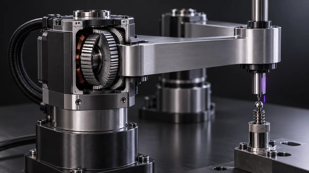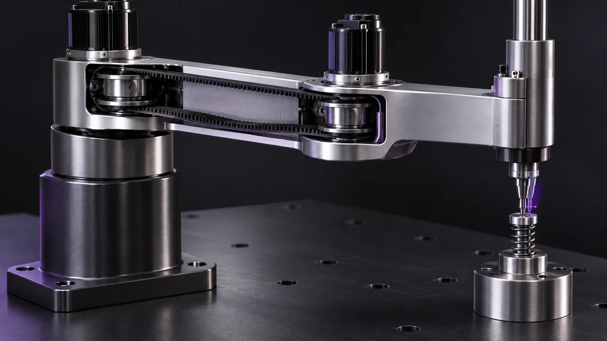
What you need
Use pulley tooth counts, motor speed and torque data. Refer to the belt manufacturer’s sizing method for final hardware selection.
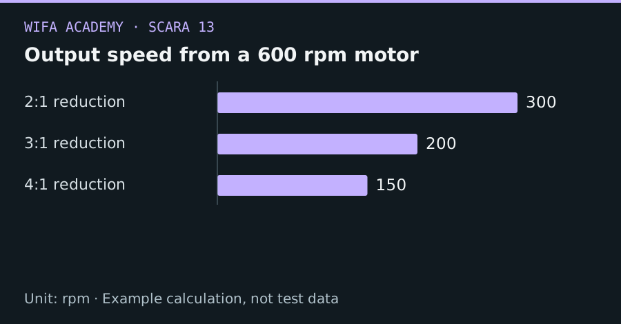
Read the diagram as a data table
| Condition or component | rpm |
|---|---|
| 2:1 reduction | 300 |
| 3:1 reduction | 200 |
| 4:1 reduction | 150 |
The calculation
G = N_driven / N_motor
ω_out = ω_motor / G
τ_out ≈ η × G × τ_motor
G is reduction ratio and η is transmission efficiency. Torque values must use compatible continuous or peak definitions.
Worked example
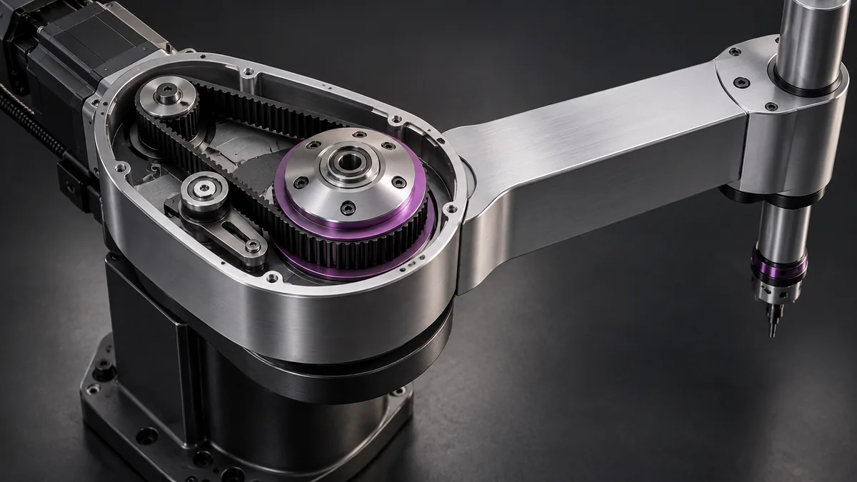
A 20-tooth motor pulley driving a 60-tooth joint pulley gives G=3. At 600 rpm motor speed, output is 200 rpm. With 0.5 N·m motor torque and illustrative η=0.9, output torque is approximately 1.35 N·m.
Try it step by step
- Choose an initial ratio from required output speed and torque, then check motor torque at the actual operating speed.
- Verify pulley size, belt wrap, tension and shaft loads against supplier guidance.
- Include the driven inertia and belt compliance in acceleration and control calculations.
- Compare predicted output motion with measured results on a restrained low-energy test setup before integrating the full arm.
How to check the result
The chosen transmission must satisfy speed, torque, thermal and mechanical requirements together, not only the static ratio calculation.
Common mistake to avoid
Stepper torque generally changes with speed. Multiplying holding torque by the gear ratio can greatly overstate usable dynamic torque.
Reference reading
Primary references for the underlying models, APIs or application context. The worked numbers and plots above are educational calculations, not results reported by these sources.