What you need
Use measured output torque and angular deflection or an initial stiffness estimate with clear uncertainty. Keep hardware restrained and unpowered for static measurements.
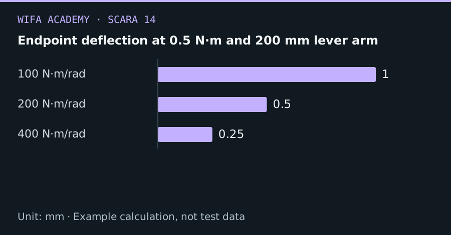
Read the diagram as a data table
| Condition or component | mm |
|---|---|
| 100 N·m/rad | 1 |
| 200 N·m/rad | 0.5 |
| 400 N·m/rad | 0.25 |
The calculation
δθ = τ / k_θ
δx ≈ r × δθ
k_θ is rotational stiffness in N·m/rad, τ is N·m and r is endpoint lever arm in mm.
Worked example
At k_θ=100 N·m/rad and τ=0.5 N·m, twist is 0.005 rad. A 200 mm lever arm gives about 1 mm endpoint displacement. Doubling stiffness reduces that estimate to 0.5 mm.
Try it step by step
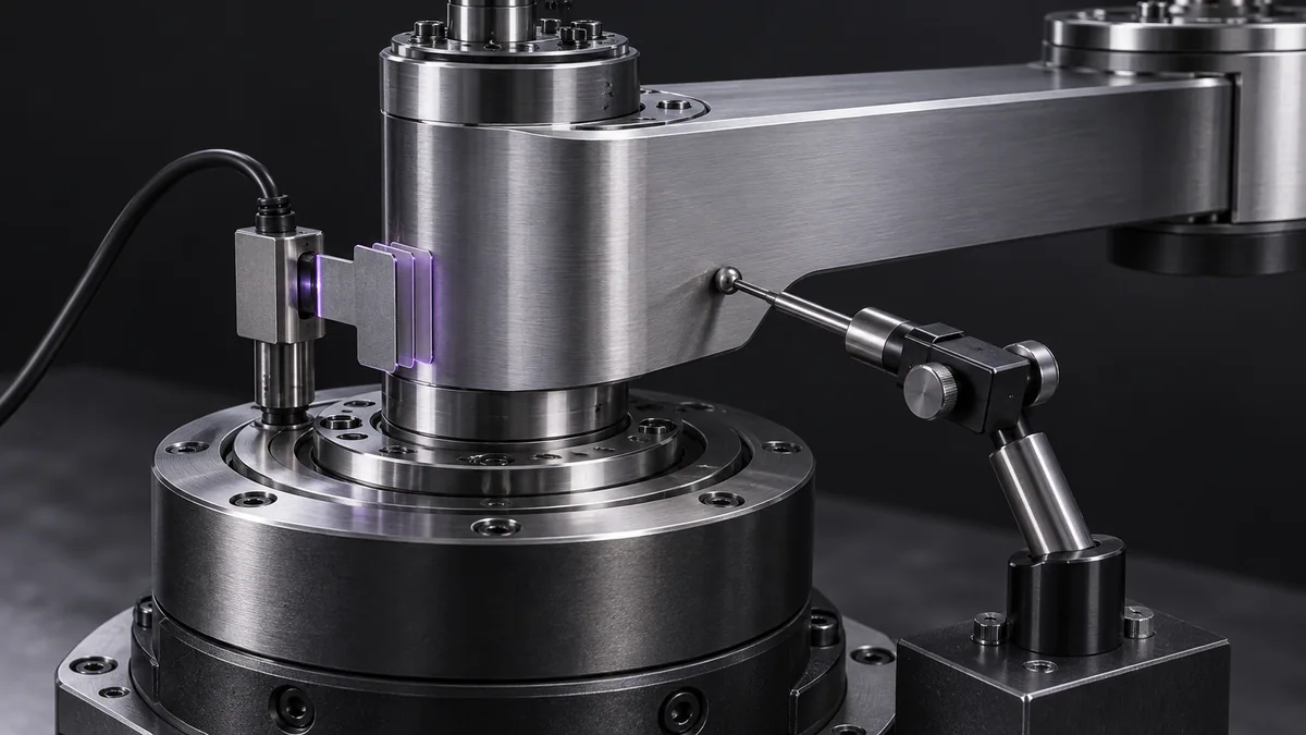
- Measure deflection at the driven joint rather than inferring it solely from motor angle.
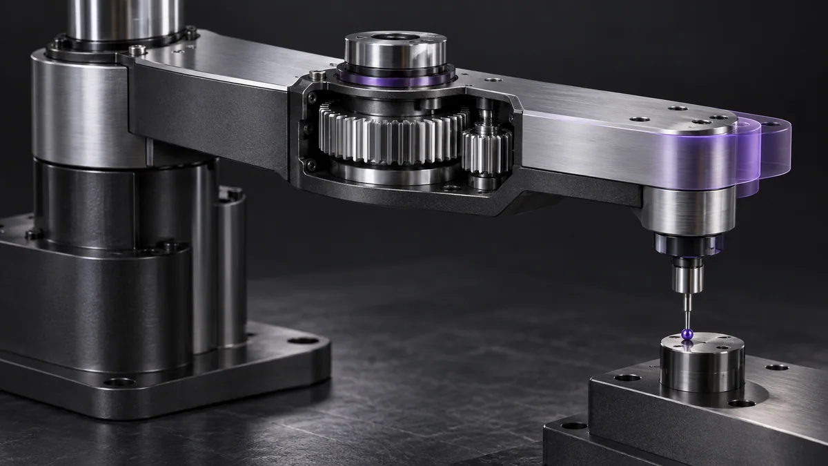
- Separate transmission compliance from link and bearing deflection by choosing suitable measurement locations.
- Estimate error at the demanding torque and pose, then compare it with the task’s error budget.
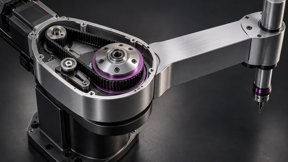
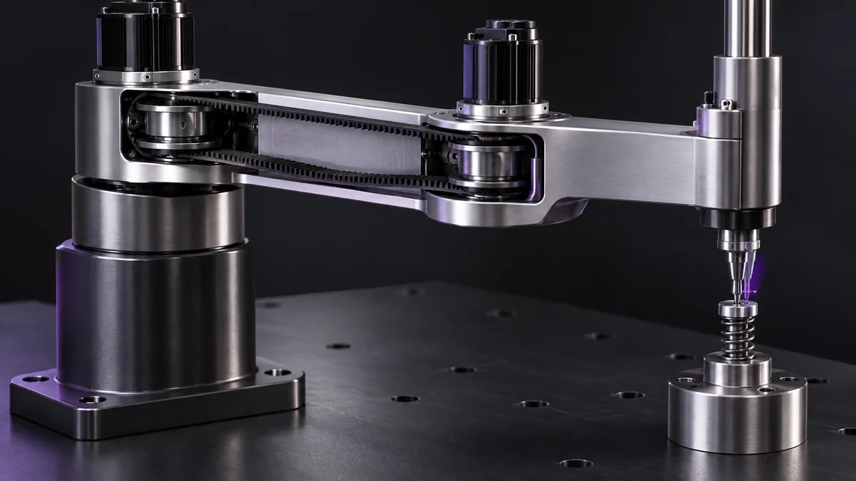
- Review belt span, tension, pulley mounting and structural stiffness using supplier constraints before changing control gains.
How to check the result
Load-unload measurements should reveal whether the behavior is approximately elastic or dominated by backlash and slip.
Common mistake to avoid
Increasing belt tension without checking bearing and belt ratings can create new failures. Software compensation cannot repair a slipping transmission.
Reference reading
Primary references for the underlying models, APIs or application context. The worked numbers and plots above are educational calculations, not results reported by these sources.