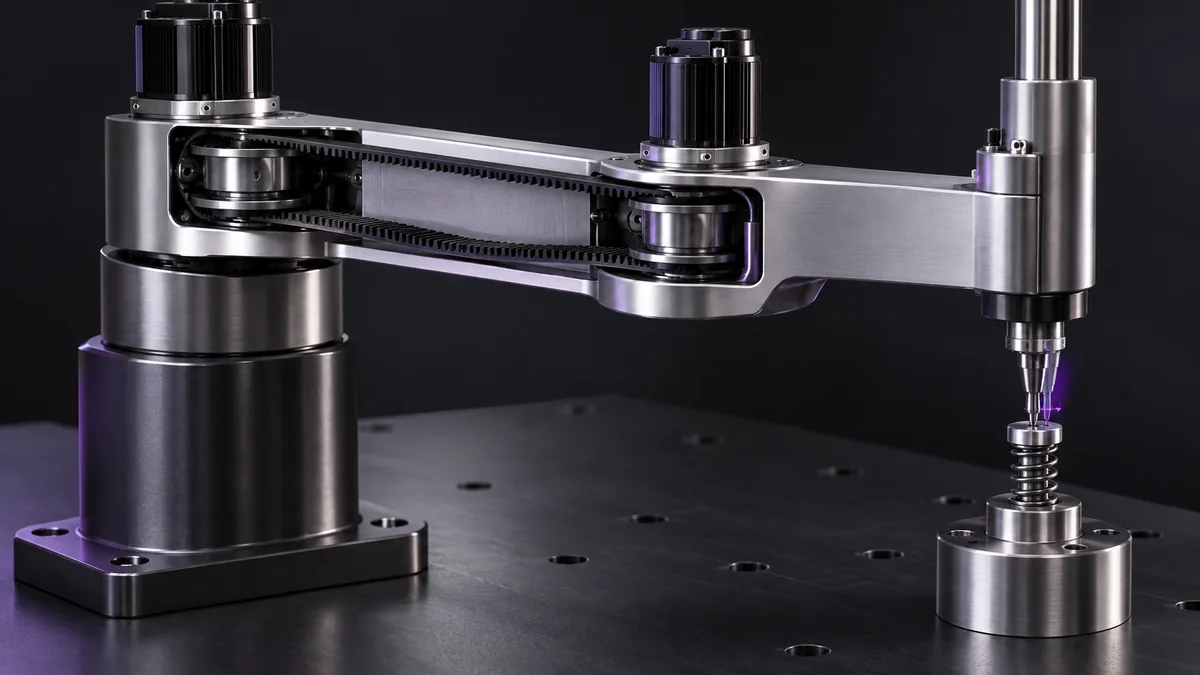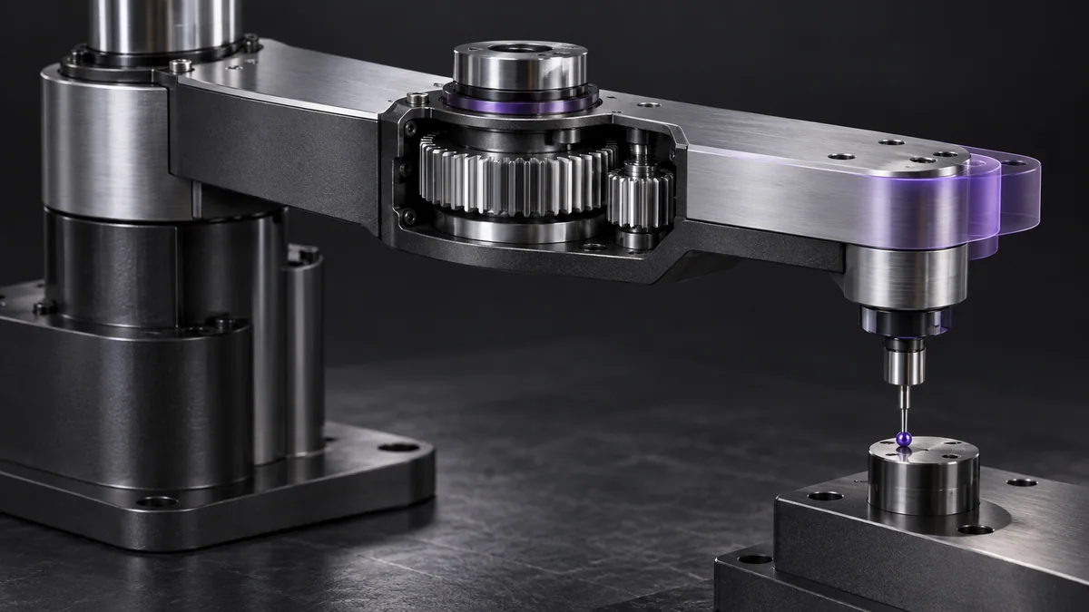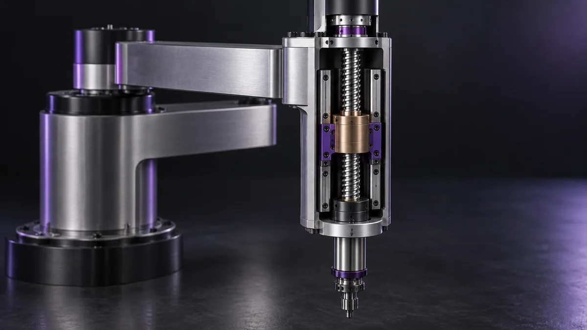
What you need
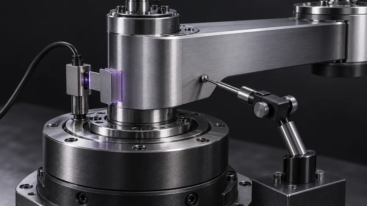
Use a protected axis, independent position measurement and the drive’s supported homing routine. Keep travel and stop protections active.
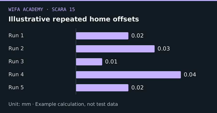
Read the diagram as a data table
| Condition or component | mm |
|---|---|
| Run 1 | 0.02 |
| Run 2 | 0.03 |
| Run 3 | 0.01 |
| Run 4 | 0.04 |
| Run 5 | 0.02 |
The calculation
range = max(x_i) − min(x_i)
x_i is measured reference position in mm or degrees. Range depends strongly on sample count and is not a complete uncertainty statistic.
Worked example
Illustrative reference readings of 0.02, 0.03, 0.01, 0.04 and 0.02 mm have a 0.03 mm range. A consistent 0.20 mm offset could still exist because repeatability and absolute reference accuracy are different.
Try it step by step
- Confirm the supported switch polarity, travel direction and maximum homing travel before any powered test.
- Use the prescribed approach, back-off and final approach sequence rather than improvising a faster routine.
- Record repeated final positions from different initial locations and separate cold and warm conditions.
- Investigate speed-dependent variation, mechanical looseness and filtering delay before adjusting the stored zero offset.
How to check the result
The complete reference test should include failed-switch and missing-transition behavior according to the approved commissioning procedure.
Common mistake to avoid
Homing is not a collision-avoidance system. A working home switch does not replace independent travel limits or appropriate safeguarding.
Reference reading
Primary references for the underlying models, APIs or application context. The worked numbers and plots above are educational calculations, not results reported by these sources.