What you need
Use a two-link simulator and inspect elbow angle along the full path, not just at its endpoints.
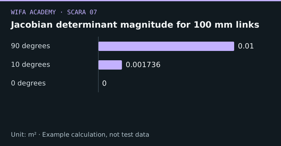
Read the diagram as a data table
| Condition or component | m² |
|---|---|
| 90 degrees | 0.01 |
| 10 degrees | 0.001736 |
| 0 degrees | 0 |
The calculation
det(J) = L₁ × L₂ × sin θ₂
For this planar position Jacobian, zero determinant indicates singularity. Determinant magnitude depends on length units and is not a universal threshold.
Worked example
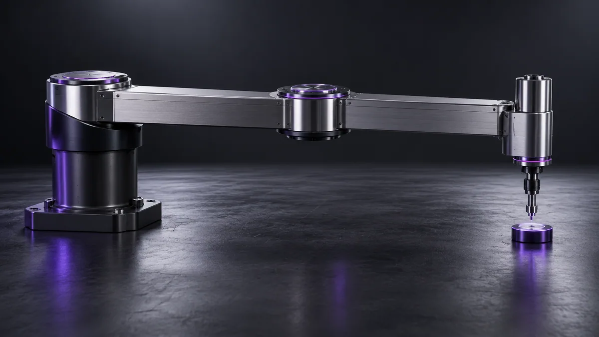
With 0.1 m links, determinant magnitude is 0.01 m² at 90°, 0.001736 m² at 10° and zero at 0°. The shrinking value warns of a loss of motion capability as the arm straightens.
Try it step by step
- Compute singularity indicators along sampled paths and mark regions near straight or fully folded configurations.
- Inspect actual required joint speeds, since a small determinant alone does not describe every direction equally.
- Move task locations away from difficult configurations or replan the path before adjusting controller limits.
- Use a suitable condition-number or singular-value analysis for more general robots and verify physical joint constraints.
How to check the result
A feasible path must respect joint speed and acceleration limits throughout motion, including near workspace edges.
Common mistake to avoid
Do not treat a nonzero determinant as proof of a well-conditioned or collision-free pose. Numerical inversion can become unstable before the determinant reaches zero.
Reference reading
Primary references for the underlying models, APIs or application context. The worked numbers and plots above are educational calculations, not results reported by these sources.