What you need
Use screw lead documentation, drive microstep settings and transmission ratio. Test calculations offline before moving a vertical load.
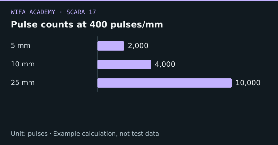
Read the diagram as a data table
| Condition or component | pulses |
|---|---|
| 5 mm | 2,000 |
| 10 mm | 4,000 |
| 25 mm | 10,000 |
The calculation
z_per_rev = lead
pulses_per_mm = N_steps × μ × G / lead
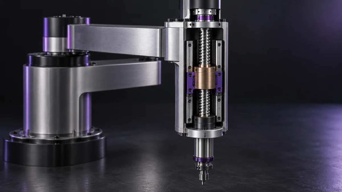
Lead is mm per screw revolution and G is motor revolutions per screw revolution. N_steps is full steps per motor revolution.
Worked example
For a 200-step motor, 16× microstepping, direct drive and 8 mm lead, the conversion is 400 pulses/mm. A 25 mm move requires 10,000 pulses. A 4 mm lead would require twice as many pulses for the same travel.
Try it step by step
- Identify screw lead from a reliable drawing or measured full-revolution travel, distinguishing it from thread spacing.
- Calculate the conversion and test several commanded distances in software with explicit sign conventions.
- Provide appropriate support or braking for the vertical load and use the approved guarded commissioning procedure.
- Verify actual travel with an independent measurement over a substantial distance and both directions.
How to check the result
Measured travel must match the configured scale, while reversal tests should separately reveal backlash or lost motion.
Common mistake to avoid
A vertical axis can fall when power is removed. Do not assume a lead screw is self-locking or that a stepper holding torque provides a fail-safe brake.
Reference reading
Primary references for the underlying models, APIs or application context. The worked numbers and plots above are educational calculations, not results reported by these sources.