What you need
Use a four-axis SCARA simulator with a defined wrist convention and a constant desired tool yaw.
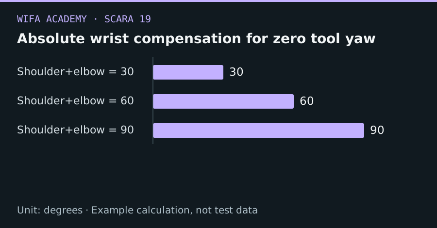
Read the diagram as a data table
| Condition or component | degrees |
|---|---|
| Shoulder+elbow = 30 | 30 |
| Shoulder+elbow = 60 | 60 |
| Shoulder+elbow = 90 | 90 |
The calculation
θ₄ = ψ_desired − θ₁ − θ₂
Angles share one unit and convention. The expression assumes an uncoupled serial yaw model; real machines may use another mapping.
Worked example
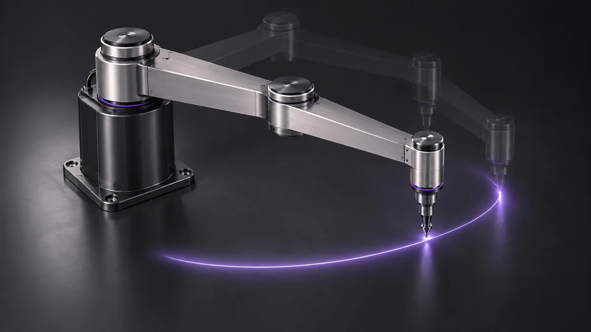
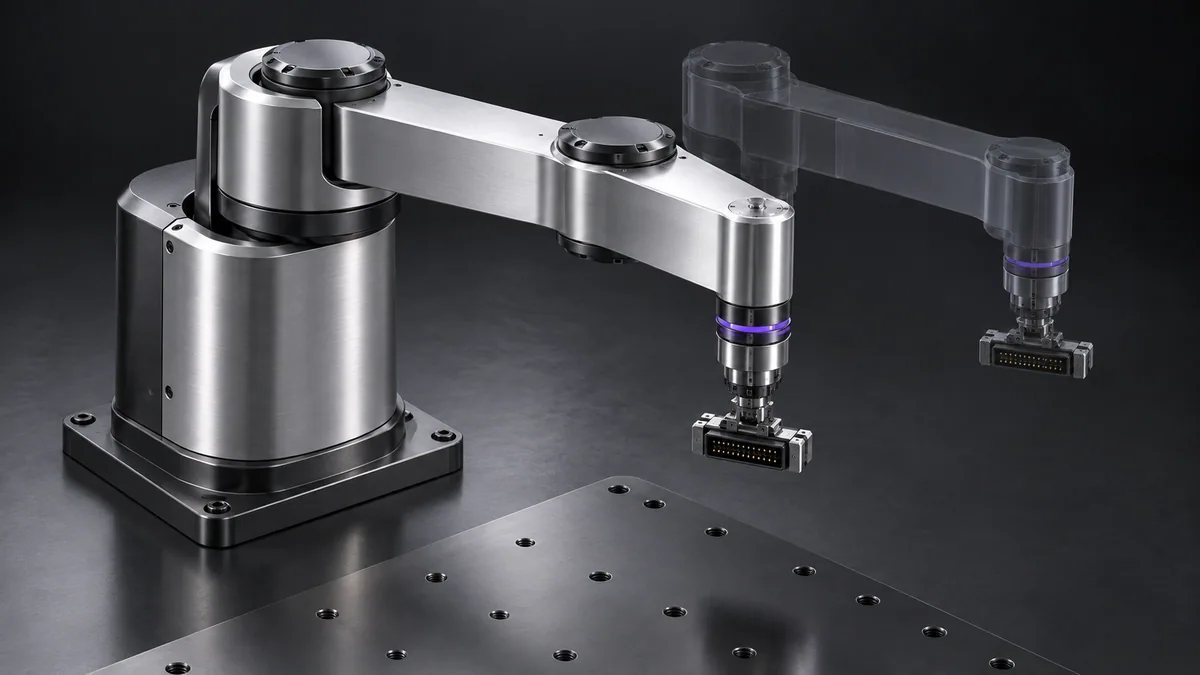
For desired yaw 0°, shoulder 20° and elbow 40°, the wrist must be -60°. If the arm moves to shoulder 35° and elbow 25°, the same wrist angle remains valid because their sum is still 60°.
Try it step by step
- Confirm the tool-yaw equation for the actual kinematic model and test it at a few simple simulated poses.
- Compute wrist compensation along the entire path, not only at endpoints.
- Choose continuous angle representations consistent with the wrist’s permitted rotation and cable limits.
- Check wrist speed and acceleration after compensation; maintaining fixed yaw can still demand substantial wrist motion.
How to check the result
Plot tool yaw throughout the path and verify that it stays within tolerance while every joint remains feasible.
Common mistake to avoid
A modulo-360 operation can hide a physically impossible cable rotation. Equivalent mathematical angles are not always equivalent robot configurations.
Reference reading
Primary references for the underlying models, APIs or application context. The worked numbers and plots above are educational calculations, not results reported by these sources.