What you need
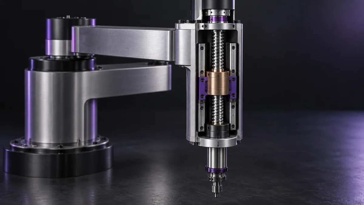
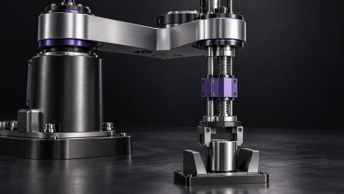
Use moving mass, screw lead, intended acceleration and supplier efficiency data. Keep any physical load supported during inspection.
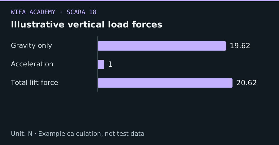
Read the diagram as a data table
| Condition or component | N |
|---|---|
| Gravity only | 19.62 |
| Acceleration | 1 |
| Total lift force | 20.62 |
The calculation
F = m × (g + a)
τ_screw = F × lead / (2π × η)
m is kg, a is upward m/s², lead is m/rev and η is screw efficiency. Torque is N·m.
Worked example
For 2 kg moving mass, a=0.5 m/s², lead=0.008 m and η=0.8, F=20.62 N and screw torque is about 0.0328 N·m. This excludes screw inertia, guide friction and transmission losses outside the efficiency model.
Try it step by step
- Weigh all moving parts, including carriage, tool, cables and the demanding workpiece variant.
- Calculate gravity and acceleration force, then use appropriate efficiency for the selected screw and operating direction.
- Add rotational inertia and measured or specified guide friction, and check continuous and peak motor capability.
- Design the vertical-axis holding and power-loss strategy separately and validate it through a competent safety process.
How to check the result
Check torque demand through the full motion cycle and verify thermal behavior, not only the upward steady-state load.
Common mistake to avoid
A low calculated lifting torque does not mean the load is safe on power loss. Backdriving and brake requirements need their own analysis.
Reference reading
Primary references for the underlying models, APIs or application context. The worked numbers and plots above are educational calculations, not results reported by these sources.