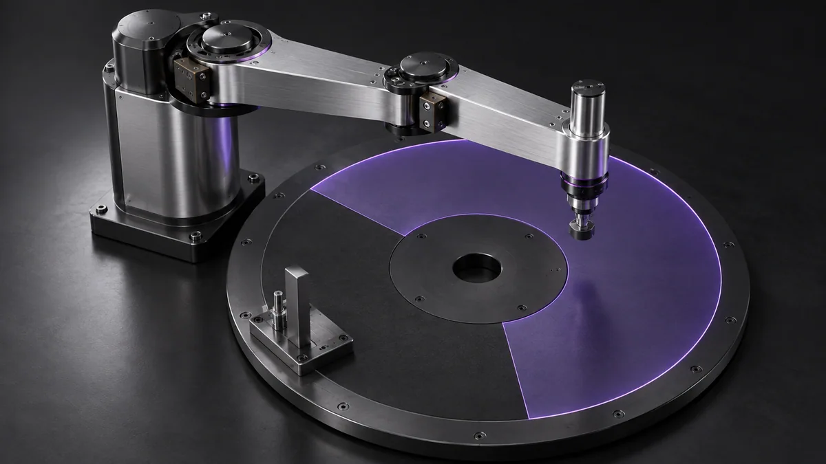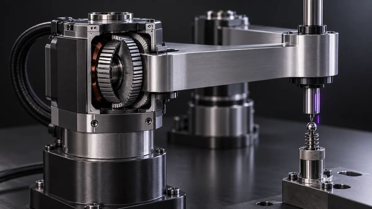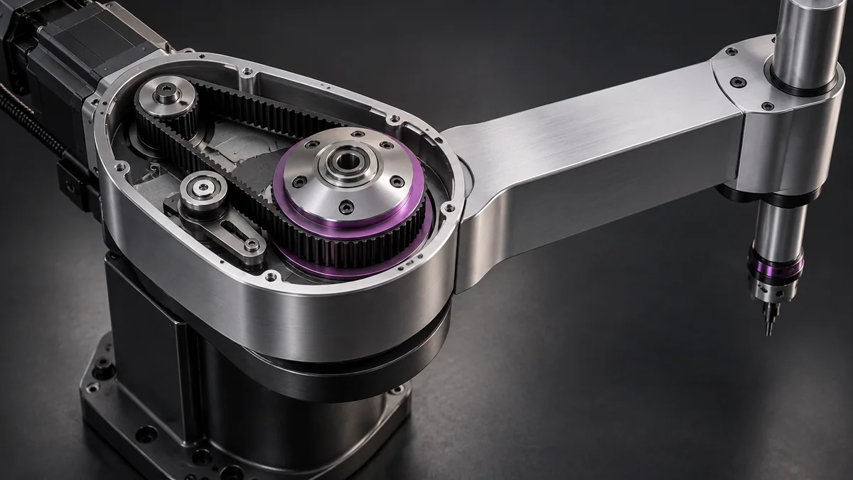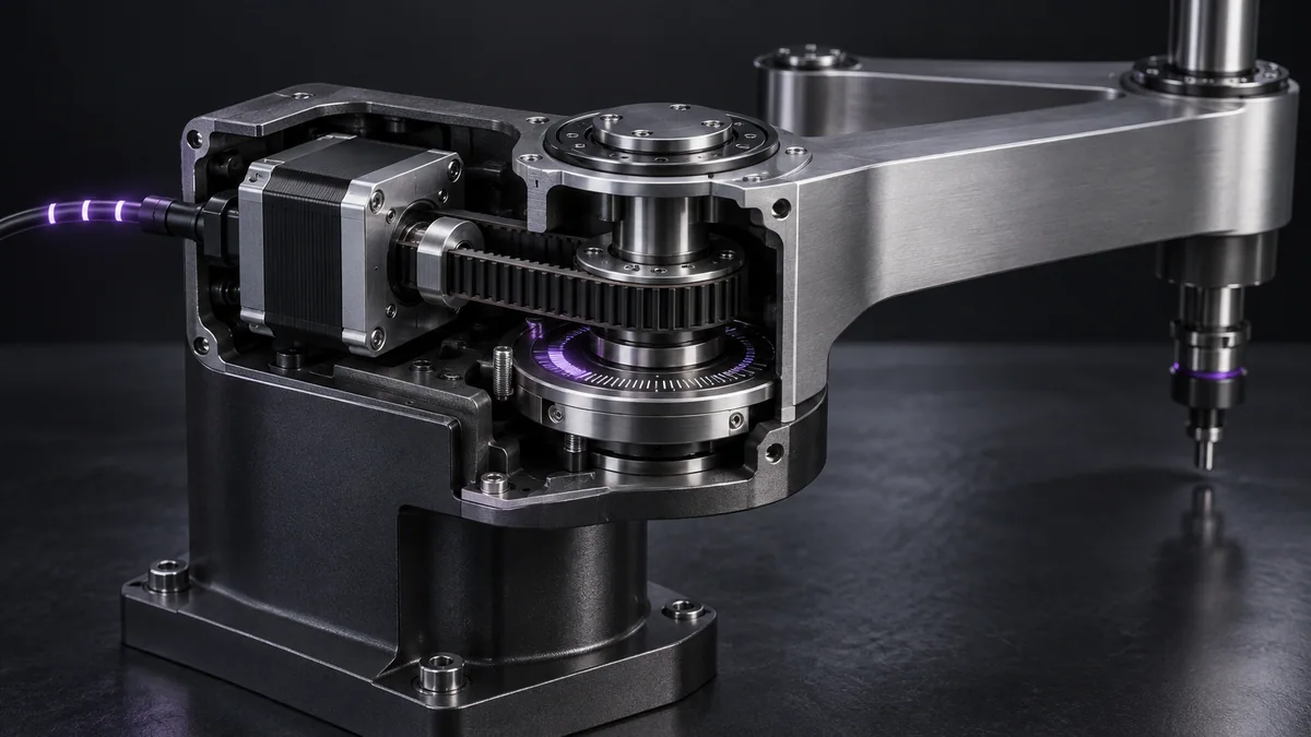
What you need
Use the motor step angle, configured microstepping and measured transmission ratio. Begin with an offline conversion test.
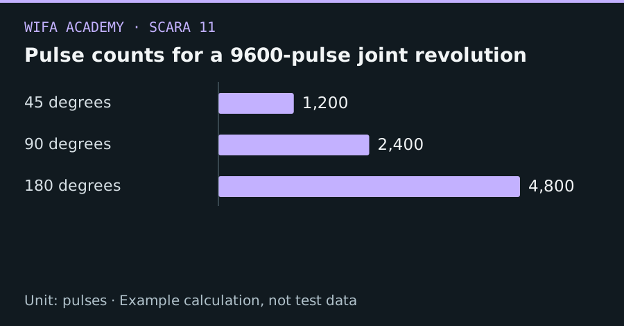
Read the diagram as a data table
| Condition or component | pulses |
|---|---|
| 45 degrees | 1,200 |
| 90 degrees | 2,400 |
| 180 degrees | 4,800 |
The calculation
N_pulses_per_rev = N_full_steps × μ × G
θ = 360° × n_pulses / N_pulses_per_rev
μ is microsteps per full step and G is motor revolutions per joint revolution. n_pulses is signed.
Worked example
A 200-step motor, 16× microstepping and 3:1 reduction gives 9,600 pulses per joint revolution. A 90° joint motion requires 2,400 pulses. The nominal angular increment is 0.0375° per pulse.
Try it step by step
- Read the drive’s actual microstep configuration and confirm the transmission ratio direction rather than relying on a label alone.
- Test conversions for zero, positive and negative quarter turns in software.
- Define rounding and accumulated fractional-pulse handling so repeated small moves do not introduce avoidable numerical drift.
- Commission direction and scale at reduced energy under a guarded procedure, using an independent angle measurement or encoder.
How to check the result
Commanded pulse counts and measured joint motion should agree over several angles and both directions within the mechanism’s actual accuracy.
Common mistake to avoid
A missed step invalidates open-loop position even when the pulse counter is correct. Microstep count is not an encoder measurement.
Reference reading
Primary references for the underlying models, APIs or application context. The worked numbers and plots above are educational calculations, not results reported by these sources.