What you need
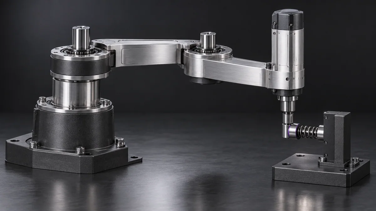
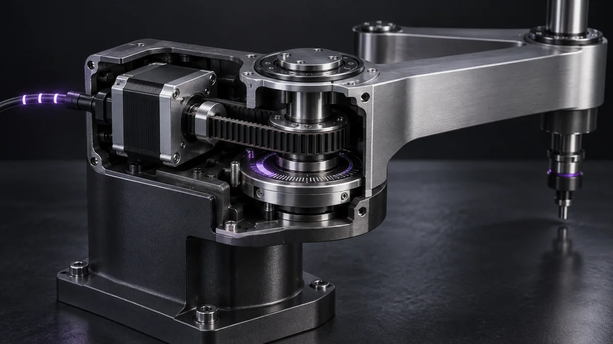
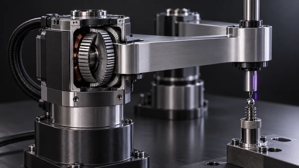
Use actual joint-limit documentation and a two-link simulator. Do not discover limits by driving an unverified mechanism into stops.
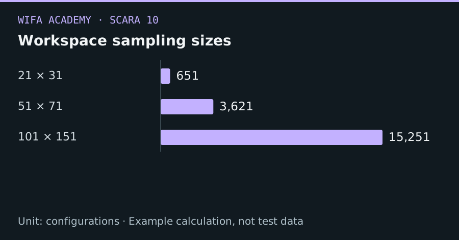
Read the diagram as a data table
| Condition or component | configurations |
|---|---|
| 21 × 31 | 651 |
| 51 × 71 | 3,621 |
| 101 × 151 | 15,251 |
The calculation
N_samples = N₁ × N₂
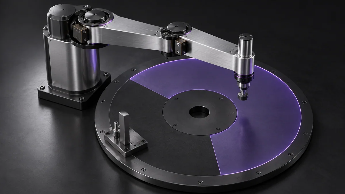
N₁ and N₂ are sample counts per joint. Sampling approximates the region and can miss narrow collision or feasibility features.
Worked example
Sampling 21 shoulder angles and 31 elbow angles produces 651 endpoint samples. Increasing to 101×151 produces 15,251 samples. The denser map looks smoother but still does not prove continuous-path feasibility.
Try it step by step
- Enter mechanical and configured limits with the correct zero positions and angle units.
- Generate a joint grid and calculate endpoints using the validated forward model.
- Remove configurations with self-collision, tool collision or unacceptable clearances, retaining configuration identity as well as position.
- Overlay required task poses and verify their connecting paths rather than accepting isolated reachable dots.
How to check the result
Check boundary samples and several known allowed and disallowed configurations independently against the model and documentation.
Common mistake to avoid
A dense endpoint cloud can hide a hole or a narrow obstacle. Sampling is a visualization aid, not a proof that a swept path is collision-free.
Reference reading
Primary references for the underlying models, APIs or application context. The worked numbers and plots above are educational calculations, not results reported by these sources.