What you need
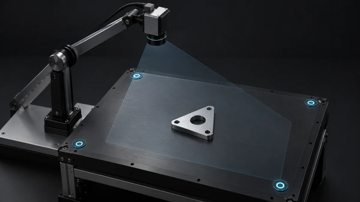
Use undistorted image points and measured table coordinates with matching point identities. Start with more than the four-point minimum.
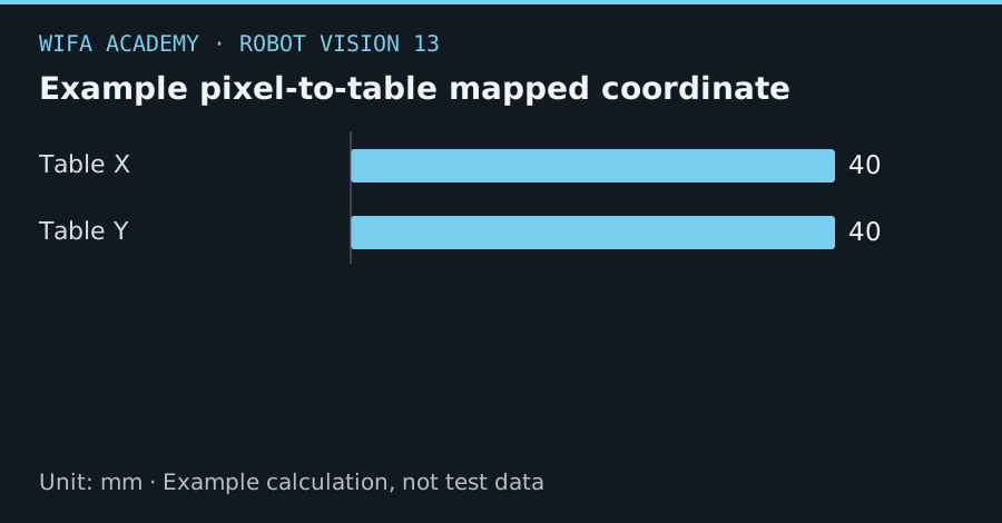
Read the diagram as a data table
| Condition or component | mm |
|---|---|
| Table X | 40 |
| Table Y | 40 |
The calculation
[x′, y′, w′]ᵀ = H × [u, v, 1]ᵀ
x = x′ / w′; y = y′ / w′
u,v are pixels and x,y are table coordinates. H is a 3×3 projective matrix; reject points when the denominator is unstable.
Worked example
For an illustrative affine special case H = [[0.1,0,10],[0,0.1,20],[0,0,1]], pixel (300,200) maps to (40,40) mm. This convenient matrix is an example, not a calibration for your camera.
Try it step by step
- Measure well-spaced non-collinear table points and associate each with its detected undistorted image coordinate.
- Estimate H using an appropriate method and examine residuals; use robust fitting when mismatches are plausible.
- Test additional known points that were not used for fitting, particularly around the picking-area boundary.
- Apply workspace bounds and reject targets on elevated surfaces unless a suitable 3D model handles the height.
How to check the result
The held-out table-coordinate errors must meet the picking tolerance. Save the calibration and its physical working-plane height together.
Common mistake to avoid
Four points can fit exactly while giving poor results elsewhere. A planar mapping applied to the top of a tall part introduces systematic position error.
Reference reading
Primary references for the underlying models, APIs or application context. The worked numbers and plots above are educational calculations, not results reported by these sources.