What you need
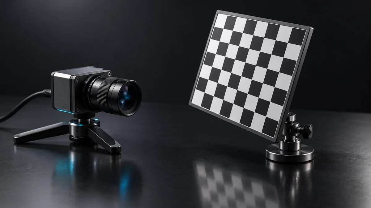
Use a calibrated camera and saved images of straight lines extending across the field. Keep the raw images for comparison.
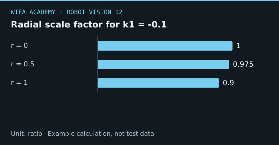
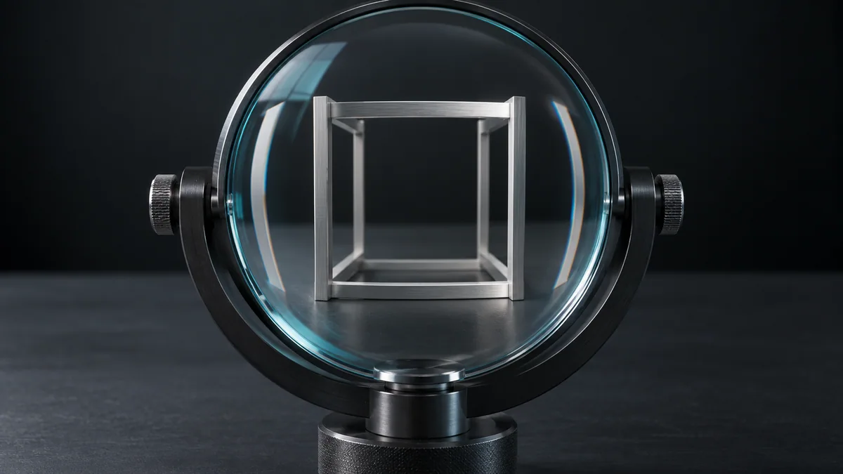
Read the diagram as a data table
| Condition or component | ratio |
|---|---|
| r = 0 | 1 |
| r = 0.5 | 0.975 |
| r = 1 | 0.9 |
The calculation
x_distorted = x × (1 + k₁r²)
y_distorted = y × (1 + k₁r²)
r² = x² + y²
x and y are normalized camera coordinates. This deliberately simplified model uses only one radial coefficient and omits tangential and higher-order terms.
Worked example
For k₁ = -0.1, a point at normalized radius 0.5 has scale factor 0.975. At radius 1 the factor is 0.9. The stronger edge effect explains why a center-only calibration check can miss important errors.
Try it step by step
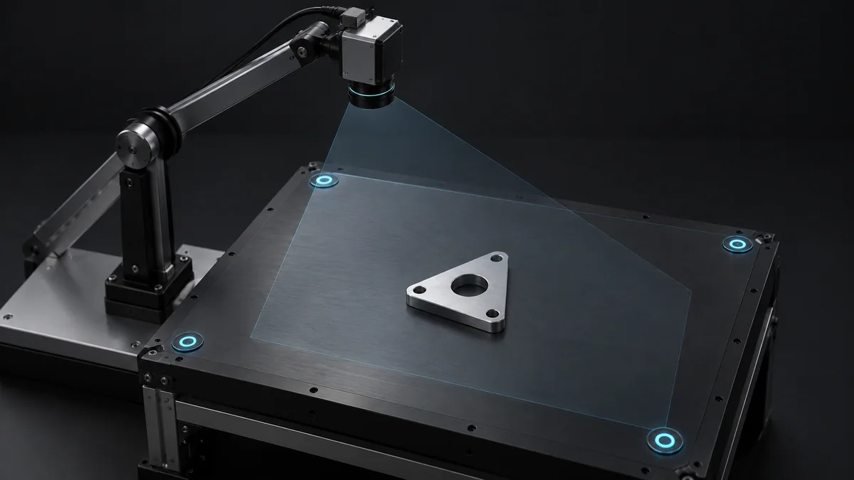
- Capture straight references near the center and edges, then verify that any observed curvature is not a bent target.
- Use the complete calibrated distortion model in the library instead of manually applying this one-term example to production images.
- Compare raw and corrected geometry, including areas cropped or resampled by the correction.
- Validate a held-out planar mapping after undistortion and use the same image-processing path at runtime.
How to check the result
Measure line straightness and target-position residuals over the complete usable field, with particular attention to corners.
Common mistake to avoid
Do not fit a distortion model from one line or use coefficients with a different intrinsic matrix. Excessive correction can be worse than the original distortion.
Reference reading
Primary references for the underlying models, APIs or application context. The worked numbers and plots above are educational calculations, not results reported by these sources.