What you need
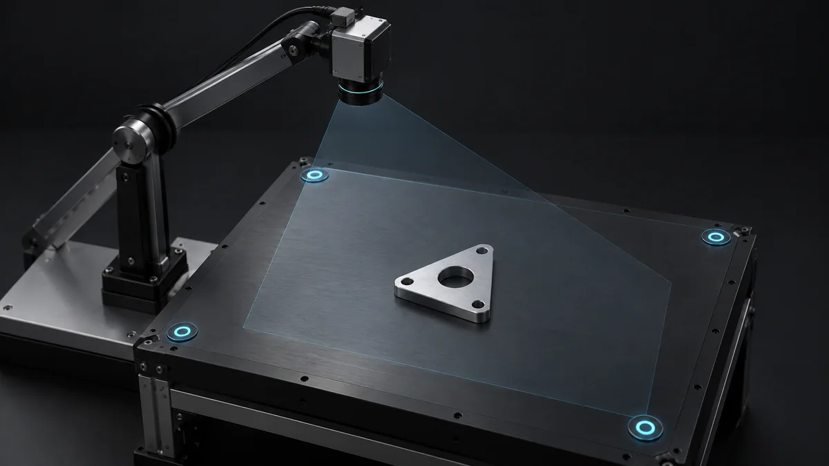
Use an offline matrix calculation and a known camera-to-base transform. Start with points whose expected position is easy to inspect.
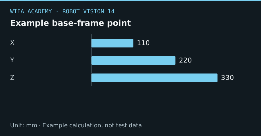
Read the diagram as a data table
| Condition or component | mm |
|---|---|
| X | 110 |
| Y | 220 |
| Z | 330 |
The calculation
p_base = T_base_camera × p_camera
p is a homogeneous column vector [x,y,z,1]ᵀ. T_base_camera converts camera coordinates into base coordinates, not the reverse.
Worked example
With identity rotation and translation (100,200,300) mm, camera point (10,20,30) becomes base point (110,220,330) mm. Applying the inverse translation instead would produce (-90,-180,-270), a very different answer.
Try it step by step
- Name every transform by its destination and source frames and record whether your software uses column or row vectors.
- Check a translation-only example, then a simple 90° rotation before combining general measured transforms.
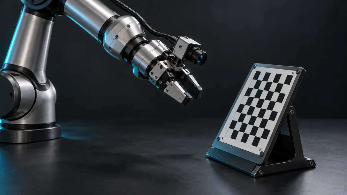
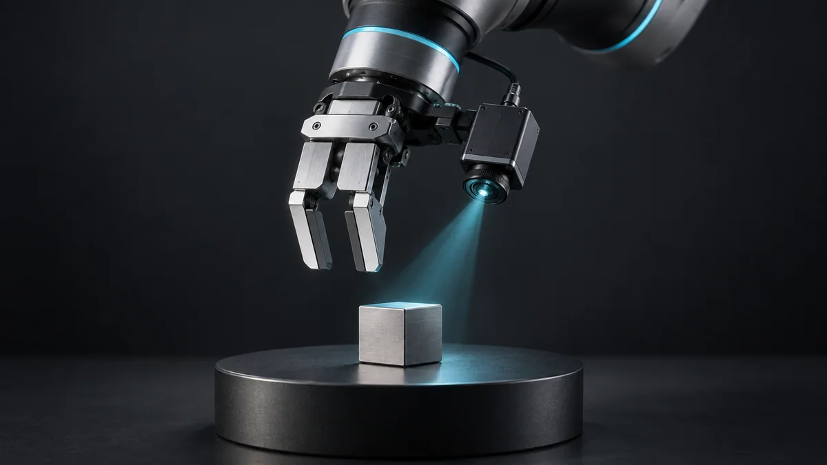
- Use consistent length units and synchronize robot pose with image capture if the camera moves with the wrist.
- Validate transformed points against independent physical references before generating any motion target.
How to check the result
Transforming a point into the other frame and back should recover the original within numerical tolerance, but also check physical references to catch a consistently wrong convention.
Common mistake to avoid
A round-trip check alone cannot prove the calibration is physically correct. Using a transform and its own inverse will pass even if both describe the wrong mounting.
Reference reading
Primary references for the underlying models, APIs or application context. The worked numbers and plots above are educational calculations, not results reported by these sources.