What you need
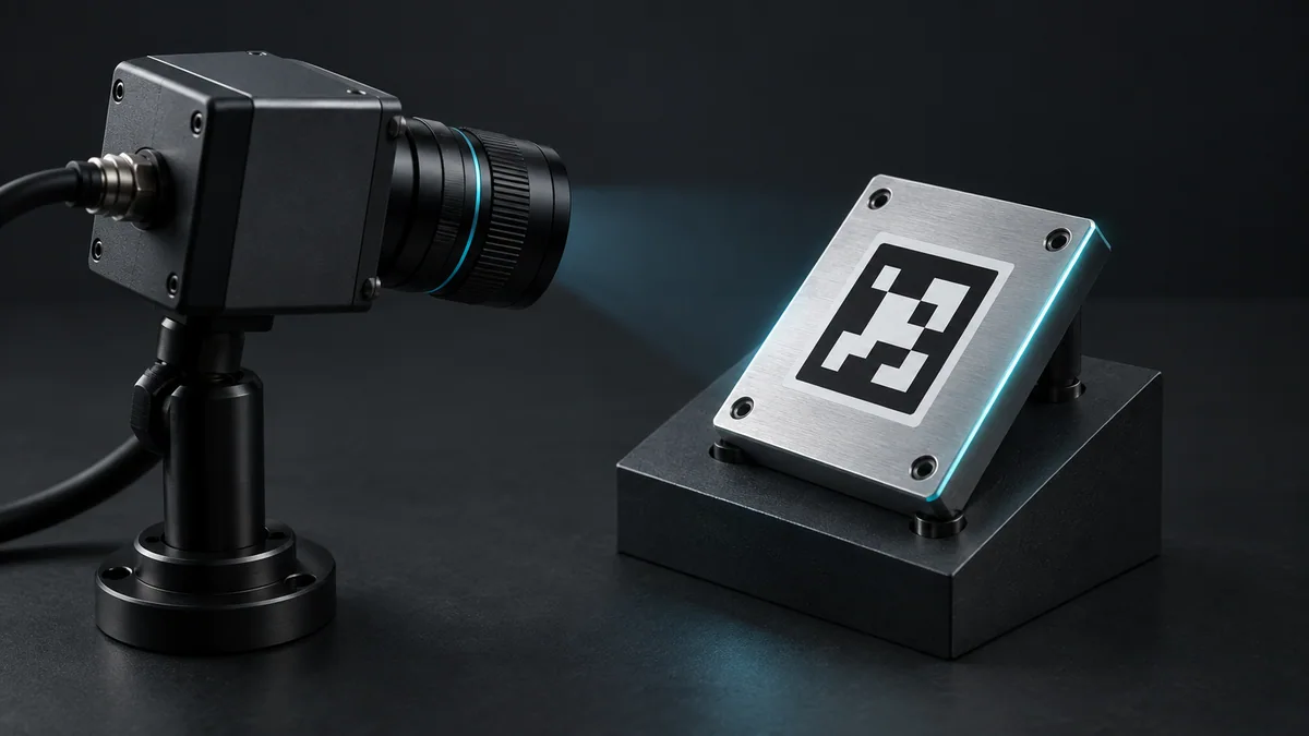
Use a rigid, accurately measured marker, fixed camera calibration and saved images. Keep the marker flat and unobstructed.
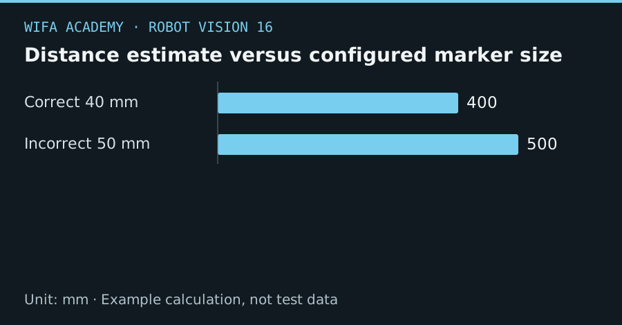
Read the diagram as a data table
| Condition or component | mm |
|---|---|
| Correct 40 mm | 400 |
| Incorrect 50 mm | 500 |
The calculation
Z ≈ f_pixels × L / p
For a front-facing marker, Z is distance, L is marker side length and p is apparent side length in pixels. This is a simplified scale check, not full pose estimation.
Worked example
A 40 mm marker spanning 80 pixels with f = 800 pixels gives approximately 400 mm distance. Entering 50 mm as the marker size would imply 500 mm instead: a 25% scale error from a printing or configuration mistake.
Try it step by step
- Measure the printed marker’s intended outer square and use the same dictionary and corner convention as the detector.
- Detect corners, estimate pose with the calibrated camera model and overlay axes on saved images.
- Define a measured marker-to-grasp transform rather than treating the marker origin as the tool target.
- Reject poor visibility, small apparent size and implausible pose jumps, then validate against known reference positions.
How to check the result
Check pose accuracy at different distances and tilts, including the smallest marker image expected in operation.
Common mistake to avoid
A marker ID is not an authentication mechanism. A copied marker or incorrect physical size can produce a valid detection with the wrong meaning.
Reference reading
Primary references for the underlying models, APIs or application context. The worked numbers and plots above are educational calculations, not results reported by these sources.