What you need
Use binary masks containing true small features and representative noise. Work on copies of the original masks.
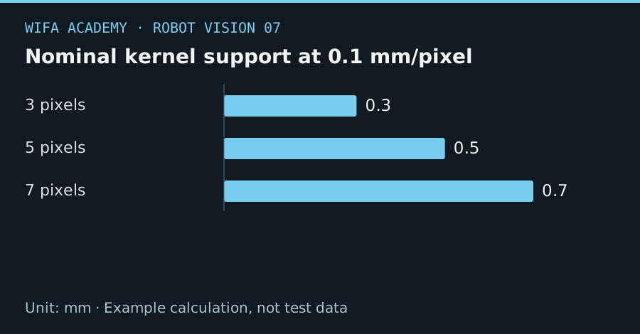
Read the diagram as a data table
| Condition or component | mm |
|---|---|
| 3 pixels | 0.3 |
| 5 pixels | 0.5 |
| 7 pixels | 0.7 |
The calculation
w_kernel ≈ k_pixels × s
k_pixels is kernel width and s is mm/pixel. This expresses nominal spatial support; the actual effect also depends on kernel shape and object geometry.
Worked example
At 0.1 mm/pixel, a 3-pixel kernel spans about 0.3 mm and a 7-pixel kernel about 0.7 mm. A narrow 0.5 mm feature can disappear under aggressive processing even though the cleaned mask looks smoother.
Try it step by step
- Keep the raw mask as a reference and mark the smallest feature that must remain visible for the robot task.
- Apply opening with a small kernel and compare removed noise with lost real structures.
- Test closing separately for unwanted holes or gaps; do not assume an opening-closing sequence is always appropriate.
- Measure centroid, area and connectivity before and after processing across the complete validation set.
How to check the result
Accept the operation only if it reduces nuisance detections without losing required geometry or shifting the target beyond the task tolerance.
Common mistake to avoid
A visually clean mask can be geometrically wrong. Increasing kernel size is not a substitute for fixing illumination or focus.
Reference reading
Primary references for the underlying models, APIs or application context. The worked numbers and plots above are educational calculations, not results reported by these sources.