What you need
Use a saved binary mask and OpenCV. Start with one isolated object and a known region of interest.
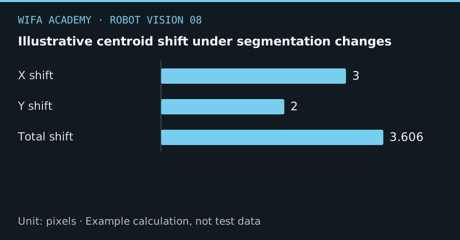
Read the diagram as a data table
| Condition or component | pixels |
|---|---|
| X shift | 3 |
| Y shift | 2 |
| Total shift | 3.606 |
The calculation
c_x = M10 / M00
c_y = M01 / M00
M00 is area or total mask weight; M10 and M01 are first moments. Coordinates are pixels and require M00 > 0.
Worked example
For M00 = 2,000, M10 = 640,000 and M01 = 480,000, the centroid is (320, 240) pixels. If a threshold shift changes the result to (323, 242), the displacement is √13 = 3.61 pixels.
Try it step by step
- Reject an empty mask and select the intended component using area and location criteria before calculating moments.
- Compute the centroid with an explicit zero-area check and draw it over the original image for inspection.
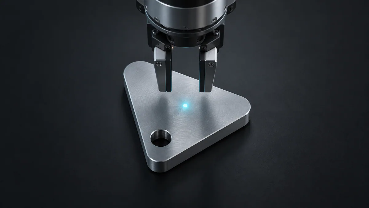
- Confirm the point lies in a usable grasp region with enough clearance for the fingers or suction cup.
- Transform the accepted point through a validated camera-to-workplane mapping and reject targets outside the allowed process region.
Offline starter code
This snippet processes local data only; it sends no robot commands.
import cv2
mask = cv2.imread("mask.png", cv2.IMREAD_GRAYSCALE)
if mask is None:
    raise FileNotFoundError("mask.png")
M = cv2.moments(mask, binaryImage=True)
if M["m00"] <= 0:
    raise ValueError("No foreground: do not create a robot target")
print(M["m10"] / M["m00"], M["m01"] / M["m00"])
How to check the result
Compare centroid repeatability over repeated captures and inspect difficult parts where the center is not a physical surface.
Common mistake to avoid
Bounding-box center and area centroid are different. Neither automatically finds a stable grasp point for a hollow or irregular part.
Reference reading
Primary references for the underlying models, APIs or application context. The worked numbers and plots above are educational calculations, not results reported by these sources.