What you need
Use a clean mask of one elongated part and a numerical array library. Visualize results on saved images.
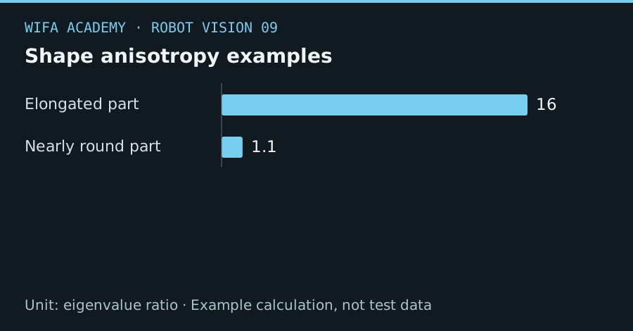
Read the diagram as a data table
| Condition or component | eigenvalue ratio |
|---|---|
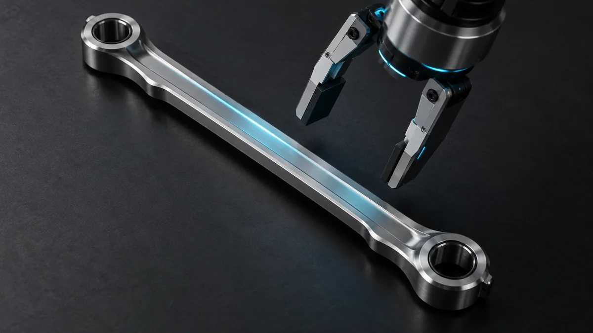
| Elongated part | 16 |
| Nearly round part | 1.1 |
The calculation
θ = atan2(v_y, v_x)
r_shape = λ_max / λ_min
v is the dominant covariance eigenvector. Eigenvalues describe spread in pixel²; the ratio is undefined if the minor eigenvalue is zero.
Worked example
A dominant vector (0.866, 0.5) gives 30°. Eigenvalues 400 and 25 yield a ratio of 16, suggesting strong elongation. Values 110 and 100 yield only 1.1, making a stable orientation much harder to infer.
Try it step by step
- Extract foreground coordinates from one valid component and subtract their mean before computing covariance.
- Find the eigenvector associated with the largest eigenvalue and overlay the axis through the centroid.
- Define the 180° ambiguity explicitly; a symmetric part’s main axis does not identify which end is which.
- Reject near-round or poorly segmented cases and validate orientation error against manually checked reference images.
How to check the result
Test rotations across the full required angle range and confirm the reported direction is continuous under your chosen angle convention.
Common mistake to avoid
Image y commonly points downward. Mixing image and robot angle conventions can reverse the commanded rotation.
Reference reading
Primary references for the underlying models, APIs or application context. The worked numbers and plots above are educational calculations, not results reported by these sources.