What you need
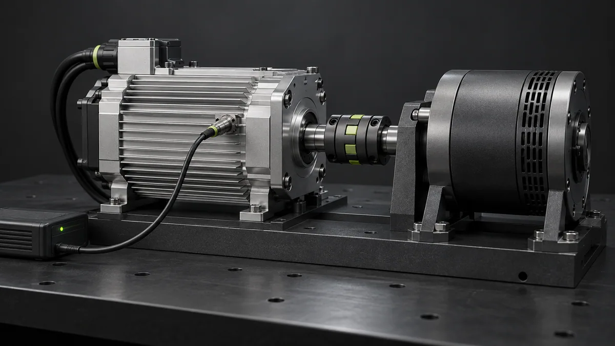
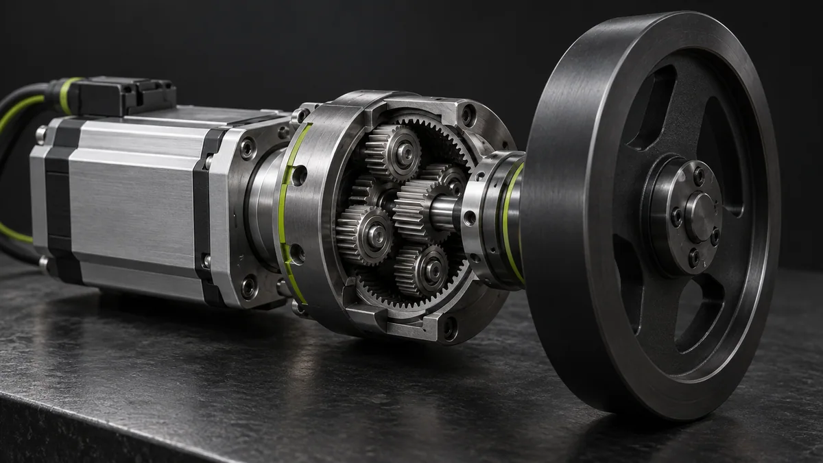
Use load inertia about the output axis, motor inertia and the defined motor-to-output speed ratio.
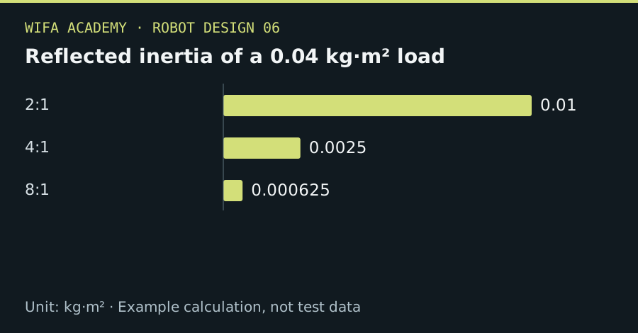
Read the diagram as a data table
| Condition or component | kg·m² |
|---|---|
| 2:1 | 0.01 |
| 4:1 | 0.0025 |
| 8:1 | 0.000625 |
The calculation
J_reflected = J_load / G²
G is motor revolutions per output revolution. J is kg·m²; motor and gearbox inertias must be added at the correct shaft reference.
Worked example
A 0.04 kg·m² load reflected through 2:1 reduction becomes 0.01 kg·m² at the motor. At 4:1 it becomes 0.0025 kg·m². The higher ratio also reduces output speed and may add more transmission effects.
Try it step by step
- Calculate load inertia about the driven axis and confirm the reduction-ratio convention.
- Reflect it to the motor shaft and add motor and gearbox inertia using supplier data.
- Check required motor speed, acceleration torque and thermal load over the actual trajectory.
- Compare alternative ratios using the whole system, including backlash, stiffness, efficiency and practical output speed.
How to check the result
The selected ratio should meet speed and torque needs without relying on an unrealistic motor operating point.
Common mistake to avoid
A lower reflected inertia is not automatically a better robot. Excessive reduction can limit speed, increase friction or reduce useful backdrivability.
Reference reading
Primary references for the underlying models, APIs or application context. The worked numbers and plots above are educational calculations, not results reported by these sources.