What you need
Use a time-resolved load estimate and motor continuous and peak ratings. Include holding periods and repeated cycles.
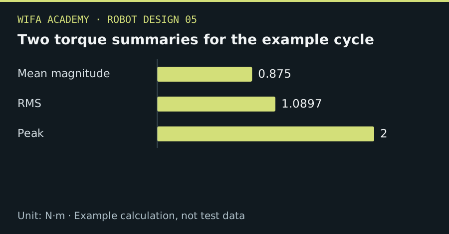
Read the diagram as a data table
| Condition or component | N·m |
|---|---|
| Mean magnitude | 0.875 |
| RMS | 1.0897 |
| Peak | 2 |
The calculation
τ_RMS = √[Σ(τ_i² × t_i) / Σt_i]
τ_i is N·m and t_i is s. The simple relationship assumes comparable cooling and motor behavior over the cycle.
Worked example
A cycle with 2 N·m for 1 s and 0.5 N·m for 3 s has RMS torque √[(4+0.75)/4] = 1.09 N·m. Its average magnitude is only 0.875 N·m, which understates the squared-current heating tendency.
Try it step by step
- Break the complete repeated cycle into torque and duration intervals, including dwell and any gravity-holding load.
- Compute RMS torque and maximum torque separately, keeping their different roles clear.
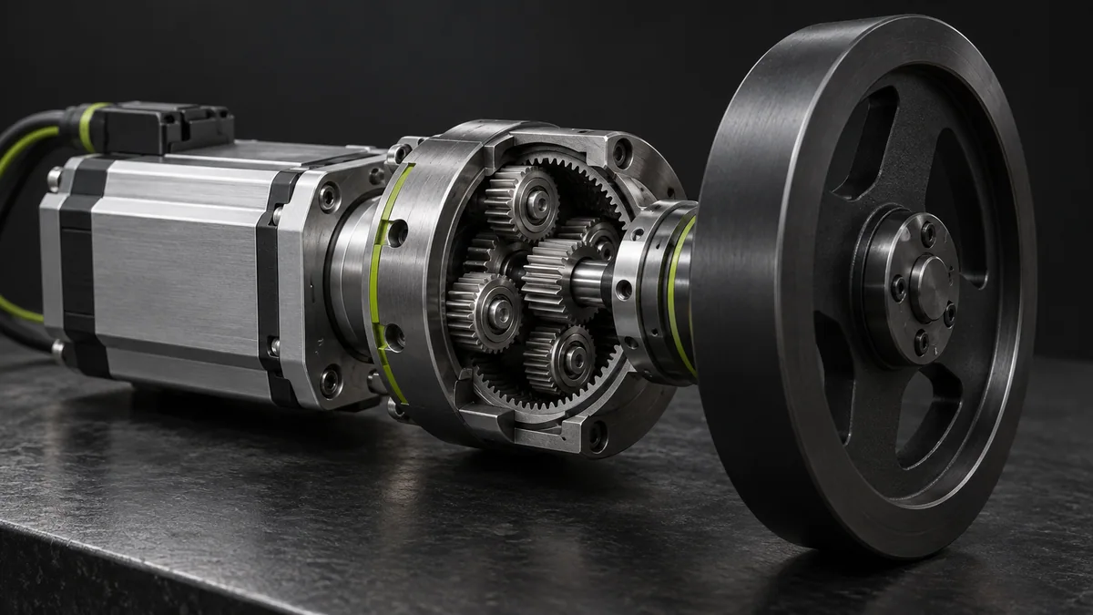
- Check motor speed, drive current, cooling, ambient temperature and gearbox duty limits at the same operating points.
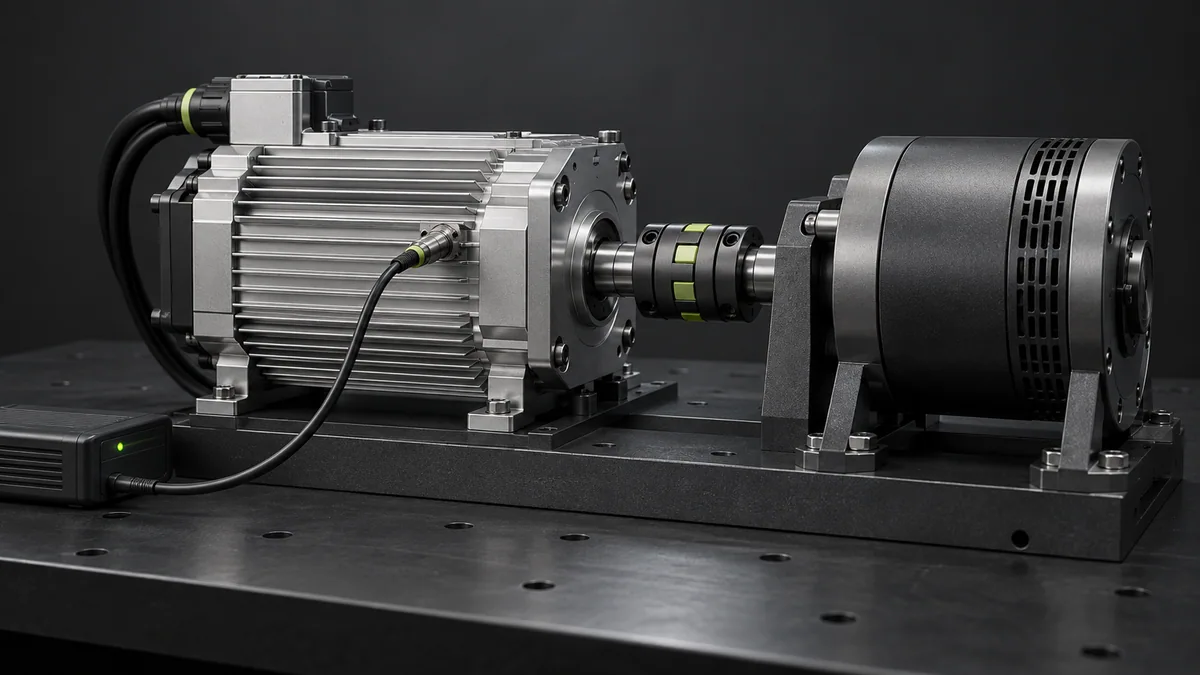
- Validate thermal behavior with a supervised controlled test and stop at documented limits rather than waiting for thermal shutdown.
How to check the result
The actuator must satisfy both peak demands and sustained thermal conditions over the intended duty cycle.
Common mistake to avoid
RMS torque alone is insufficient when speed-dependent losses or cooling changes dominate. Do not compare output-shaft torque directly with a motor-shaft rating.
Reference reading
Primary references for the underlying models, APIs or application context. The worked numbers and plots above are educational calculations, not results reported by these sources.