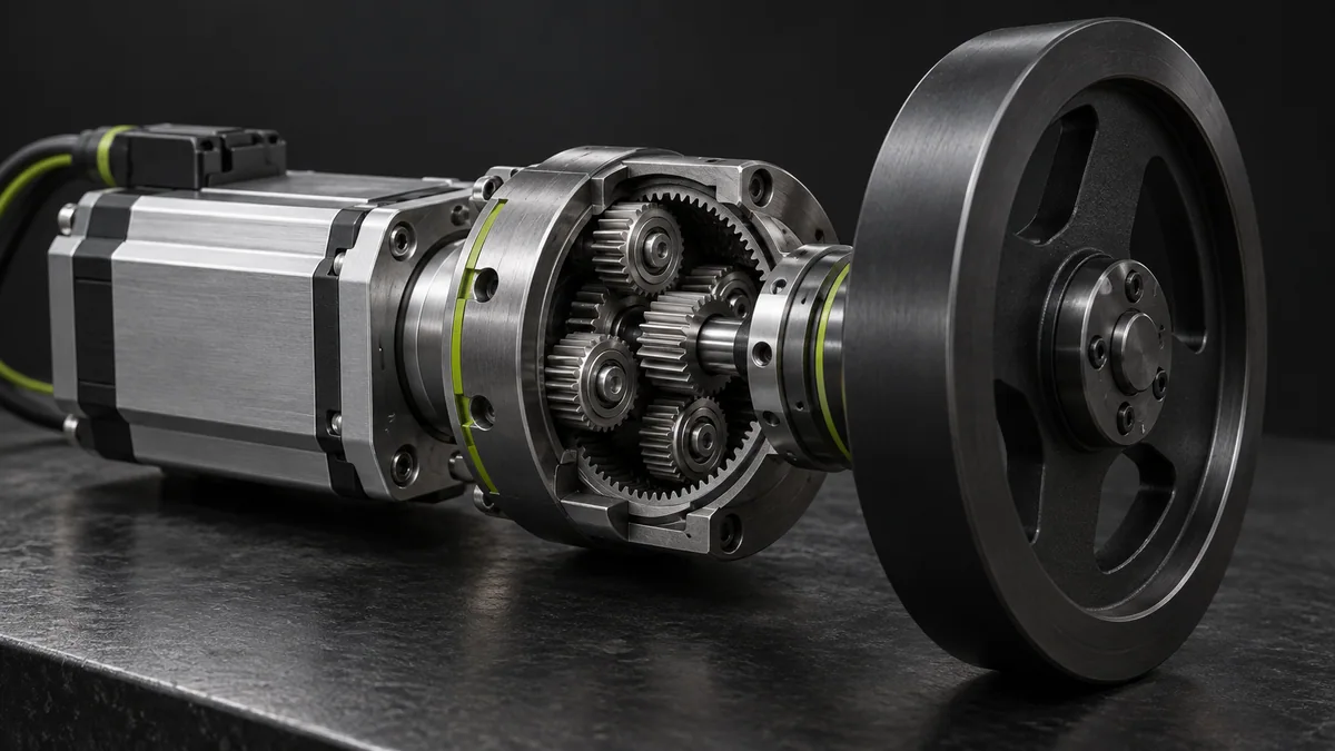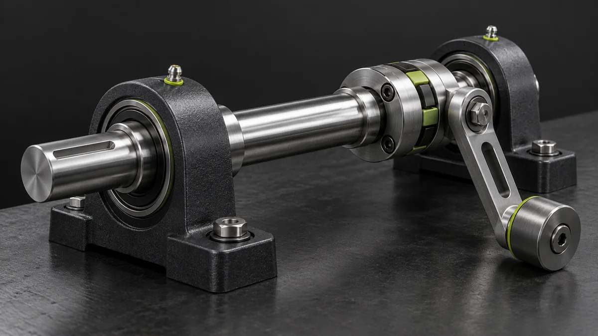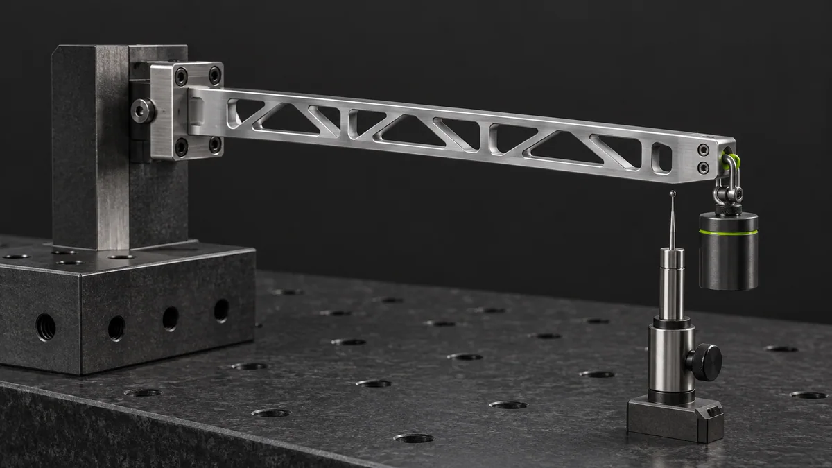
What you need
Use a straight beam approximation, material elastic modulus, section geometry and a known transverse tip load.
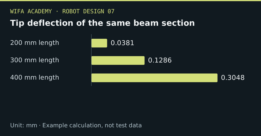
Read the diagram as a data table
| Condition or component | mm |
|---|---|
| 200 mm length | 0.0381 |
| 300 mm length | 0.1286 |
| 400 mm length | 0.3048 |
The calculation
δ_tip = F × L³ / (3 × E × I)
F is N, L is m, E is Pa and second moment I is m⁴. The model assumes small deflection, linear elasticity and a fixed cantilever support.
Worked example
For F=10 N, L=0.3 m, E=70 GPa and I=1×10⁻⁸ m⁴, deflection is 0.0001286 m, or 0.129 mm. Extending the same section to 0.4 m raises the estimate to 0.305 mm.
Try it step by step
- Choose a section and compute its second moment about the actual bending axis, not simply its area.
- Estimate the demanding transverse load and apply the model only where the support and geometry are comparable.
- Compare stiffness changes from shorter length, deeper section or different material before adding mass indiscriminately.
- Validate with a restrained static deflection test or a more complete structural model including joints and mounts.
How to check the result
Check both deflection and stress; a part can remain below yield while being too flexible for accurate positioning.
Common mistake to avoid
Joint compliance and mounting flexibility often dominate a neat beam calculation. Printed polymers also have direction- and time-dependent properties.
Reference reading
Primary references for the underlying models, APIs or application context. The worked numbers and plots above are educational calculations, not results reported by these sources.