What you need
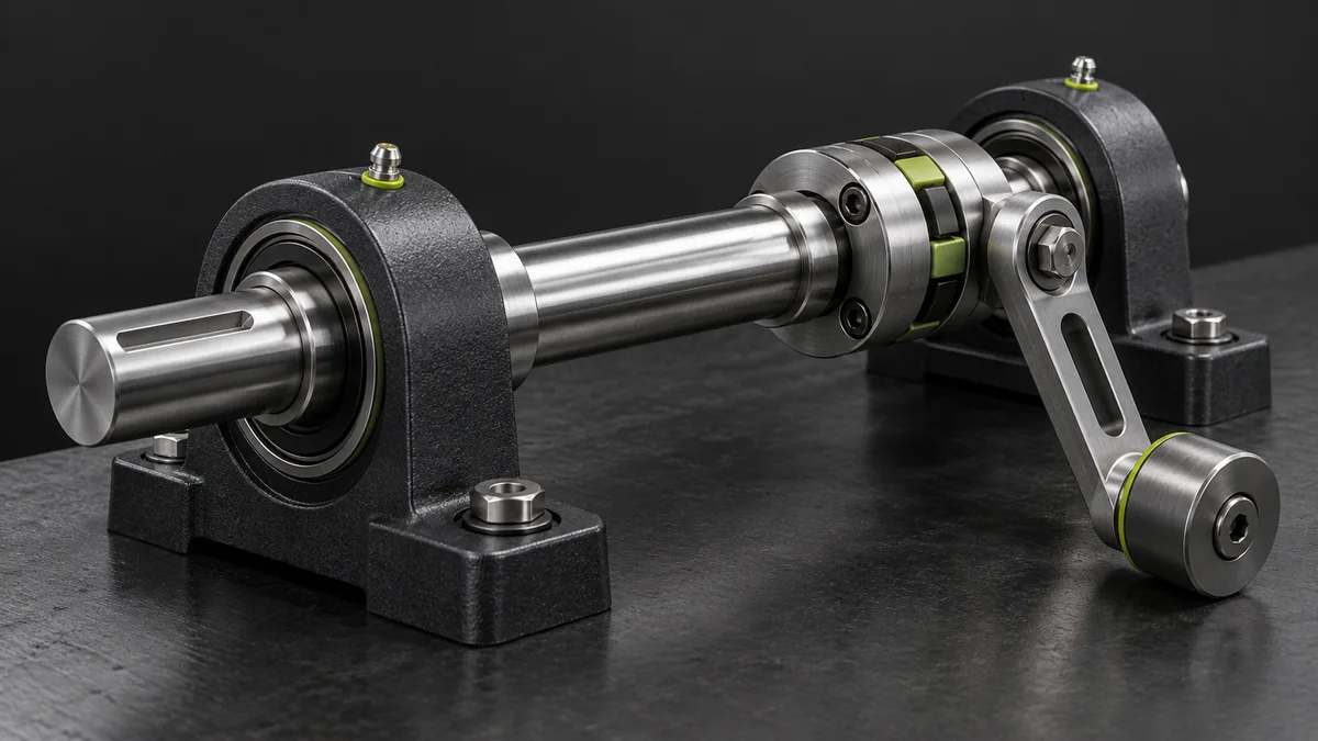
Use a preliminary torque estimate and solid circular shaft geometry. Final design needs material data and the actual stress concentrations.
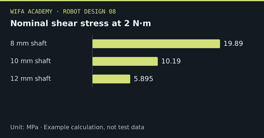
Read the diagram as a data table
| Condition or component | MPa |
|---|---|
| 8 mm shaft | 19.89 |
| 10 mm shaft | 10.19 |
| 12 mm shaft | 5.895 |
The calculation
τ_max = 16T / (πd³)
Here τ_max is shear stress in Pa, T is applied torque in N·m and d is shaft diameter in m. This is not the joint-torque symbol used elsewhere.
Worked example
For T=2 N·m and d=10 mm, nominal maximum shear stress is about 10.19 MPa. At 8 mm diameter it rises to 19.89 MPa. A modest diameter reduction nearly doubles the nominal stress.
Try it step by step
- Determine peak transmitted torque and relevant reversing or cyclic loads rather than using only average motor torque.
- Compute nominal stress for candidate diameters with explicit unit conversion.
- Account for keyways, shoulders, fits, bending and fatigue using suitable design methods and material properties.
- Check torsional deflection, bearing support and manufacturability before approving the shaft geometry.
How to check the result
A design review should identify stress concentration locations and both strength and stiffness criteria.
Common mistake to avoid
Do not compare this nominal stress directly with a tensile yield number without the appropriate failure criterion and design factors.
Reference reading
Primary references for the underlying models, APIs or application context. The worked numbers and plots above are educational calculations, not results reported by these sources.