What you need
Use a software simulator or a low-energy controller bench with actuators disconnected. Define fault handling before enabling the watchdog.
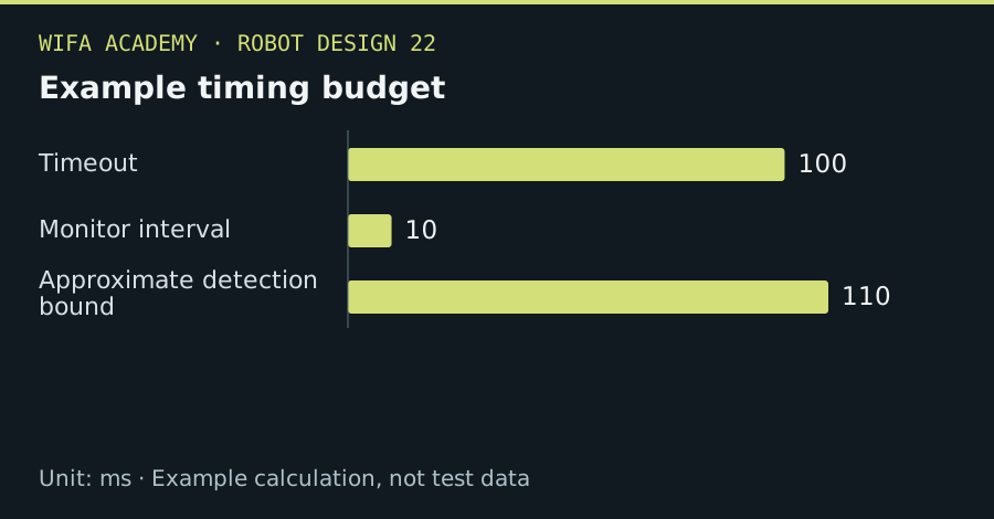
Read the diagram as a data table
| Condition or component | ms |
|---|---|
| Timeout | 100 |
| Monitor interval | 10 |
| Approximate detection bound | 110 |
The calculation
t_detect_max ≈ t_timeout + t_check
t_timeout is the configured missing-progress interval and t_check is the maximum delay before the monitoring task evaluates it.
Worked example
With a 100 ms timeout and a monitor checked every 10 ms, detection may take about 110 ms after the last valid progress update. Restart and actuator response add further delay; they are not included in this simple estimate.
Try it step by step
- Define what completion of a healthy control cycle means and refresh the watchdog only after those checks succeed.
- Inject a blocked task, missed sensor update and communications failure in the bench setup.
- Design the fault response so outputs and stored state do not create an unintended automatic restart.
- Check recovery, logging and repeated-fault behavior, keeping machinery-safety functions independent of an ordinary application watchdog.
How to check the result
The test record should show the fault injection time, detection time and final output state for each failure mode.
Common mistake to avoid
A watchdog reset does not guarantee safe motion cessation. A reboot can itself create hazards if outputs or power-loss behavior are not properly designed.
Reference reading
Primary references for the underlying models, APIs or application context. The worked numbers and plots above are educational calculations, not results reported by these sources.