What you need
Use measured mass, CAD dimensions and a robot description format supported by your simulator. Keep collision geometry simple but representative.
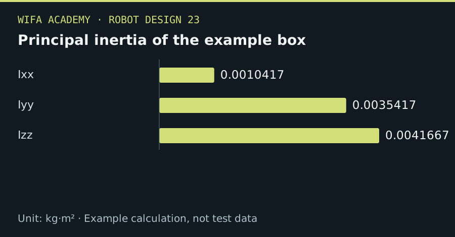
Read the diagram as a data table
| Condition or component | kg·m² |
|---|---|
| Ixx | 0.0010417 |
| Iyy | 0.0035417 |
| Izz | 0.0041667 |
The calculation
I_xx = m(b²+c²)/12
I_yy = m(a²+c²)/12
I_zz = m(a²+b²)/12
These are center-of-mass principal inertias of a uniform box with side lengths a,b,c in m and mass m in kg.
Worked example
A 1 kg box of 0.2×0.1×0.05 m has inertias I_xx=0.001042, I_yy=0.003542 and I_zz=0.004167 kg·m². Entering millimeters as meters would multiply squared-length terms by one million.
Try it step by step
- Measure or estimate each link’s mass and locate its center of mass relative to the link frame.
- Calculate inertias in SI units, using CAD for complex shapes and the parallel-axis theorem when shifting reference points.
- Inspect joint axes, limits and collision geometry separately from the visual mesh.
- Run a simple gravity or acceleration test and compare its trend with a hand calculation before trusting complex simulation results.
How to check the result
The model should have physically plausible inertia values and reproduce simple expected behavior without artificial instability from invalid parameters.
Common mistake to avoid
A visually detailed mesh does not make dynamics accurate. Avoid zero or arbitrary tiny inertias used only to silence simulator warnings.
Reference reading
Primary references for the underlying models, APIs or application context. The worked numbers and plots above are educational calculations, not results reported by these sources.