What you need
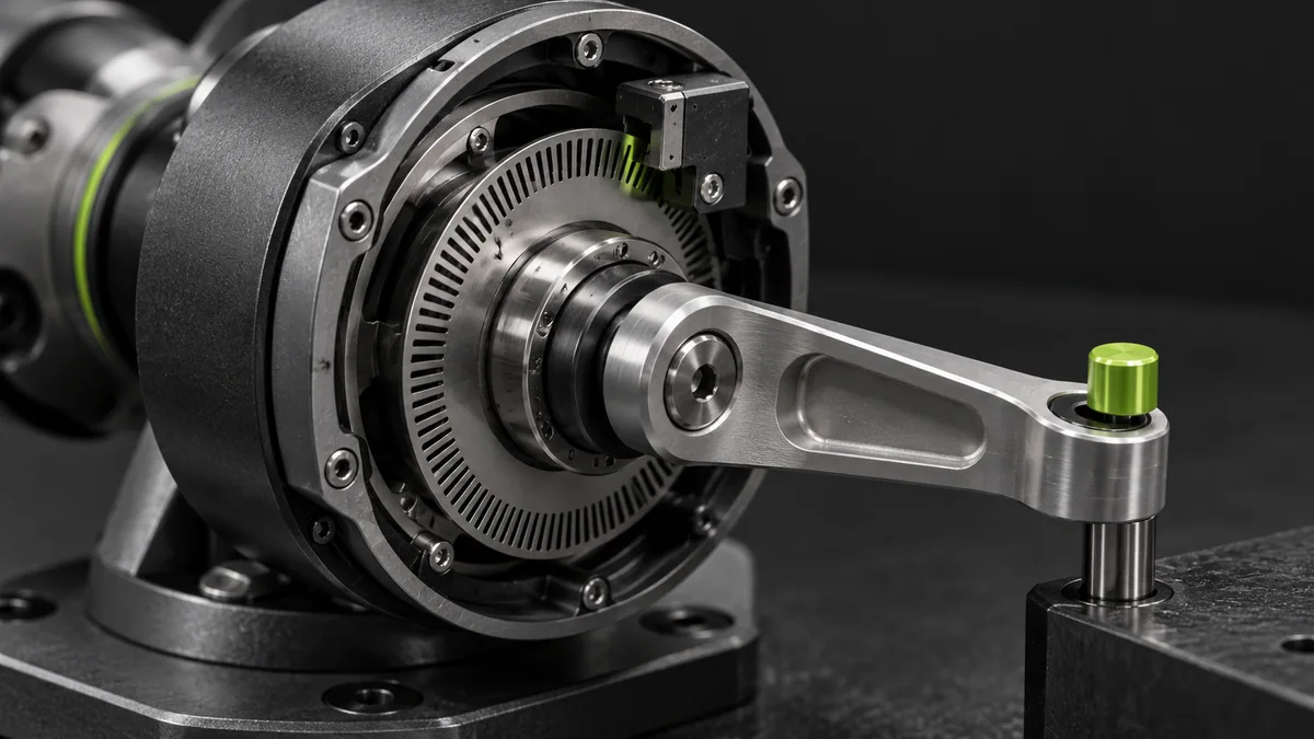
Use the encoder’s documented decoded counts per revolution and the sensor’s physical mounting location.
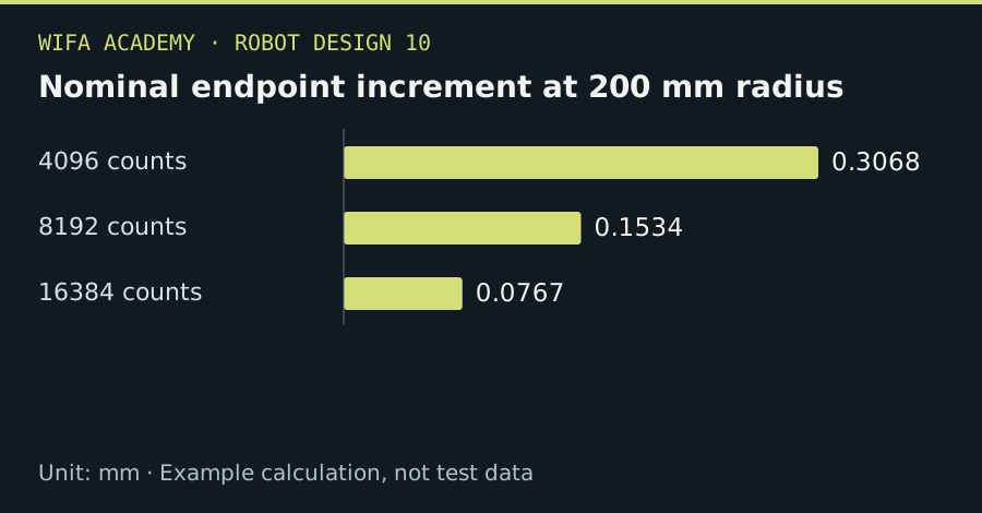
Read the diagram as a data table
| Condition or component | mm |
|---|---|
| 4096 counts | 0.3068 |
| 8192 counts | 0.1534 |
| 16384 counts | 0.0767 |
The calculation
δθ = 2π / N_counts
δx ≈ r × δθ
N_counts is the actual count total after the chosen decoding. r is a local lever arm; do not confuse cycles, pulses and quadrature counts.
Worked example
At 4,096 counts/revolution, the increment is 0.08789°. At a 200 mm lever arm this is about 0.307 mm. At 16,384 counts it becomes approximately 0.0767 mm, before other errors.
Try it step by step
- Read the supplier’s count convention and verify the firmware’s actual increment over one complete revolution.
- Account for gearing if the encoder is motor-mounted and identify motion that occurs downstream of the sensor.
- Convert nominal quantization into local endpoint sensitivity at demanding robot poses.
- Measure actual positioning and repeatability rather than presenting the quantization increment as achieved accuracy.
How to check the result
A full-turn test should return the expected count change, and reversal tests should expose any downstream lost motion.
Common mistake to avoid
A motor encoder cannot directly observe gearbox backlash or a slipping output coupling. More counts do not fix an unmeasured mechanical error.
Reference reading
Primary references for the underlying models, APIs or application context. The worked numbers and plots above are educational calculations, not results reported by these sources.