What you need
Use robot mass, wheel radius, intended acceleration and a measured or cautiously estimated rolling resistance force.
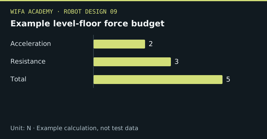
Read the diagram as a data table
| Condition or component | N |
|---|---|
| Acceleration | 2 |
| Resistance | 3 |
| Total | 5 |
The calculation
F_required = m × a + F_resistance
τ_per_wheel ≈ F_required × r / (n_driven × η)
m is kg, a is m/s², r is m, n_driven is the number of equally loaded driven wheels and η is drivetrain efficiency.
Worked example
For a 5 kg robot accelerating at 0.4 m/s² with 3 N resistance, total force is 5 N. Two driven wheels of 0.05 m radius with η=0.8 each require about 0.156 N·m under the equal-share assumption.
Try it step by step
- Measure rolling resistance on representative flooring using a restrained low-speed setup or suitable force measurement.
- Calculate acceleration demand and check the worst expected load distribution across driven wheels.
- Compare required traction with available tire-ground friction and check motor torque at the intended wheel speed.
- Test gradually in a contained clear area, measuring current, slip and stopping behavior under an approved procedure.
How to check the result
The robot should meet acceleration requirements without wheel slip or exceeding motor, drive and thermal limits.
Common mistake to avoid
Larger motor torque cannot overcome a lack of traction. Slopes, thresholds and turning resistance may exceed the simple level-floor budget.
Reference reading
Primary references for the underlying models, APIs or application context. The worked numbers and plots above are educational calculations, not results reported by these sources.