What you need
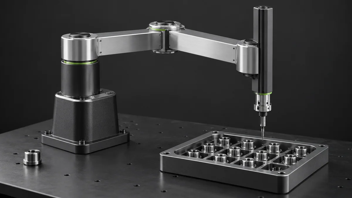
Use a measured mass list and a side-view sketch with centers of gravity. Keep any physical mechanism supported and unpowered.
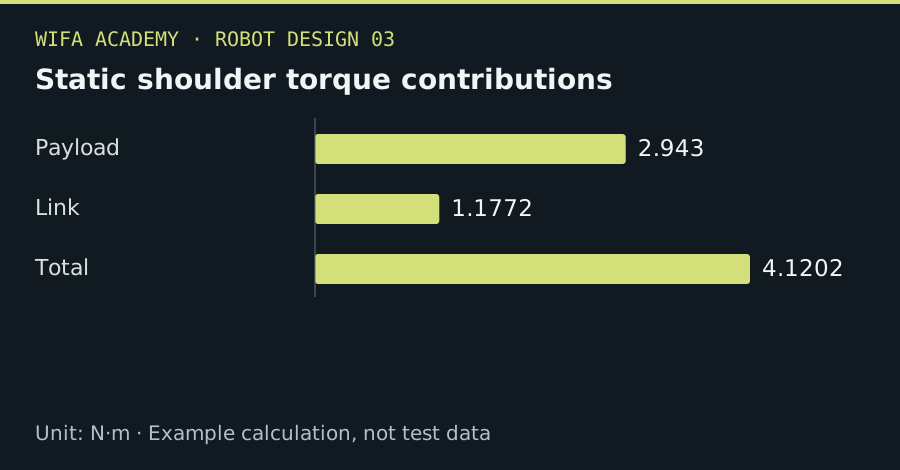
Read the diagram as a data table
| Condition or component | N·m |
|---|---|
| Payload | 2.943 |
| Link | 1.1772 |
| Total | 4.1202 |
The calculation
τ_gravity = Σ m_i × g × d_i
m_i is kg and d_i is the perpendicular horizontal lever arm in m for gravity loading. Torque is N·m.
Worked example
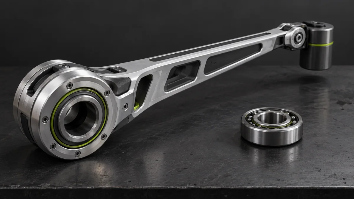
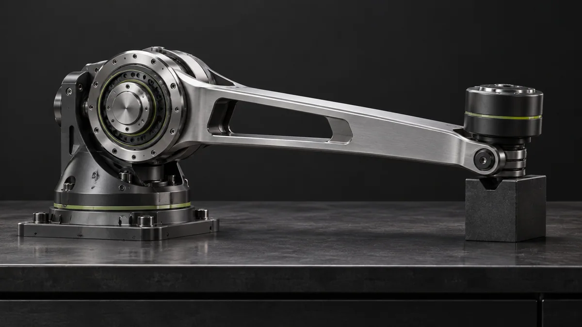
A 1 kg payload at 0.30 m contributes 2.943 N·m. A 0.8 kg link centered at 0.15 m adds 1.177 N·m, for 4.120 N·m total. Ignoring the arm mass underestimates the requirement by about 29% of the total.
Try it step by step
- Draw the demanding horizontal pose and locate every carried mass relative to the joint axis.
- Calculate each contribution separately so a design change can be traced to its effect on torque.
- Add other links, tooling, cables and off-axis components, then evaluate additional poses if their geometry is different.
- Check the full dynamic cycle against motor, gearbox, brake and structural requirements with an appropriate engineering margin.
How to check the result
Compare the calculated static moment with an independent CAD mass-properties or moment-arm calculation.
Common mistake to avoid
Holding torque is not the same as available continuous moving torque. A brake and safe power-loss strategy may be needed even when the motor can hold the arm.
Reference reading
Primary references for the underlying models, APIs or application context. The worked numbers and plots above are educational calculations, not results reported by these sources.