What you need
Use sketches of the tool’s required poses and a simple kinematic model. Include loading and maintenance positions, not only production poses.
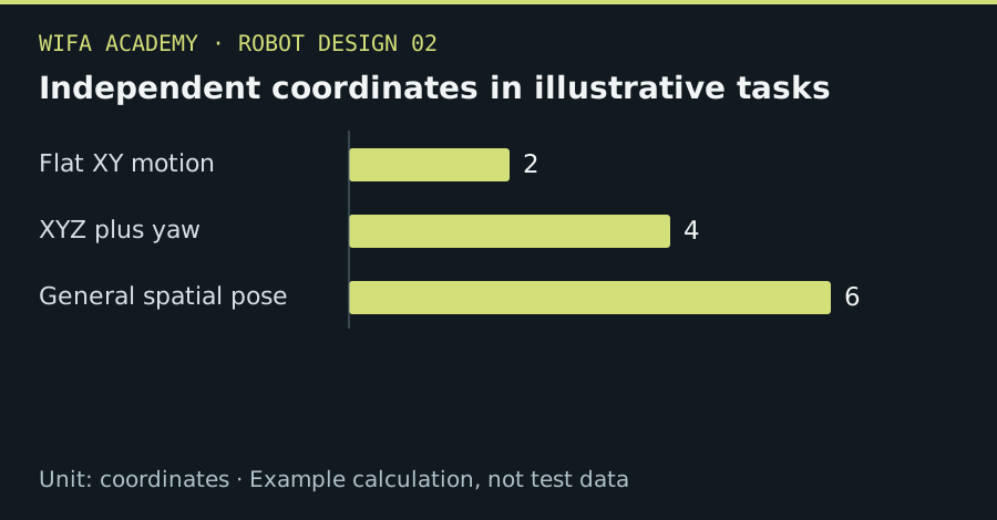
Read the diagram as a data table
| Condition or component | coordinates |
|---|---|
| Flat XY motion | 2 |
| XYZ plus yaw | 4 |
| General spatial pose | 6 |
The calculation
n_task = n_position + n_orientation
This is task-coordinate bookkeeping, not a general mechanism mobility formula. Independent unconstrained spatial pose has up to three position and three orientation coordinates.
Worked example
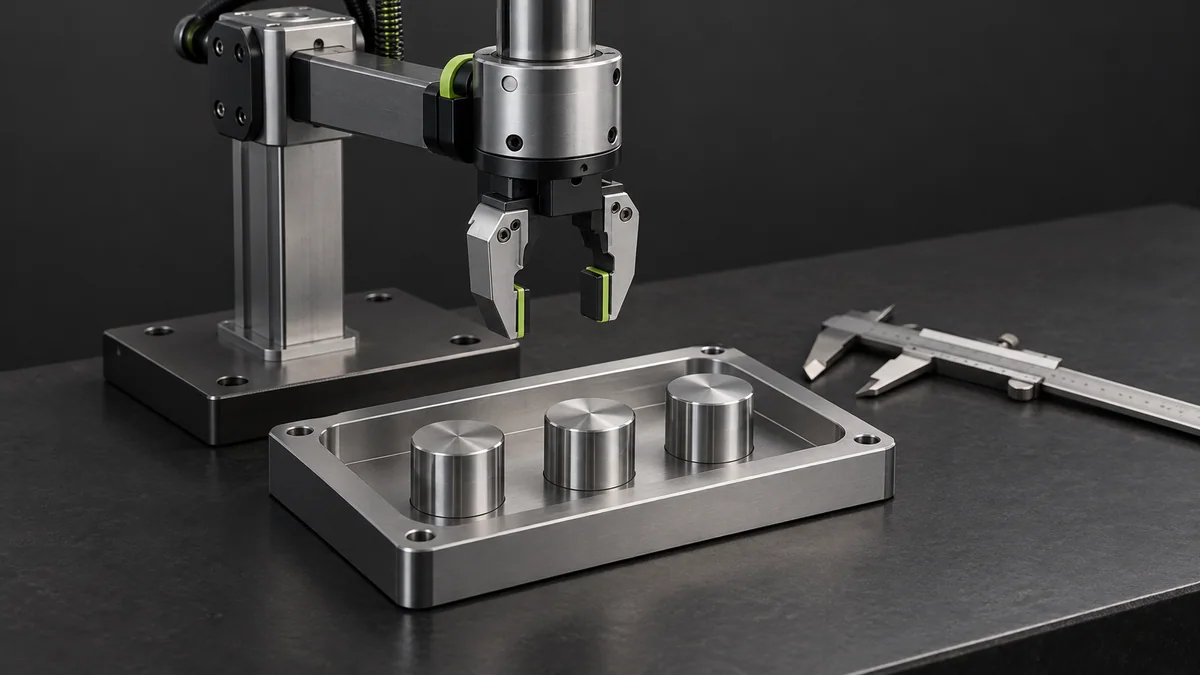
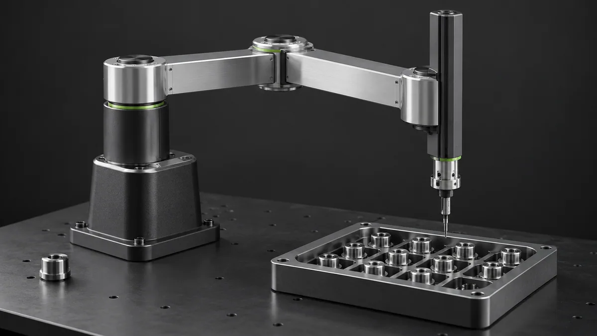
A flat pick-and-place task with variable x, y, z and yaw requires four task coordinates. Keeping height fixed and omitting rotation reduces the described task to two. These counts do not by themselves prove a chosen mechanism can reach all poses.
Try it step by step
- List every tool pose needed by the task and mark which coordinates may remain mechanically constrained.
- Compare candidate mechanisms for workspace, stiffness, payload and access, not only axis count.
- Simulate the demanding poses and connecting paths with realistic limits and obstacles.
- Identify whether extra redundancy solves a real access problem or merely adds cost and complexity.
How to check the result
Demonstrate all required poses and transitions in the selected architecture before designing detailed joints.
Common mistake to avoid
Having enough axes is necessary but not sufficient. Singularities, joint ranges and collisions can make a nominally capable robot unsuitable.
Reference reading
Primary references for the underlying models, APIs or application context. The worked numbers and plots above are educational calculations, not results reported by these sources.