What you need
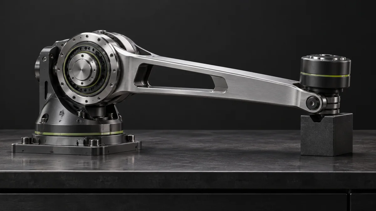
Use link dimensions, masses and intended angular acceleration. Treat the link as a uniform rod only when that approximation is reasonable.
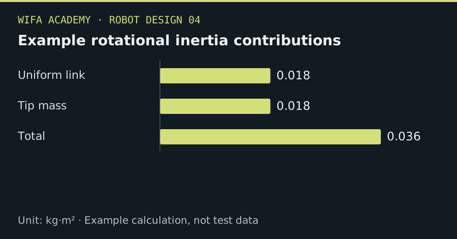
Read the diagram as a data table
| Condition or component | kg·m² |
|---|---|
| Uniform link | 0.018 |
| Tip mass | 0.018 |
| Total | 0.036 |
The calculation
J_rod_end = mL²/3
J_point = mr²
τ_accel = J_total × α
J is kg·m², lengths are m, α is rad/s² and torque is N·m. Gravity and friction are separate terms.
Worked example
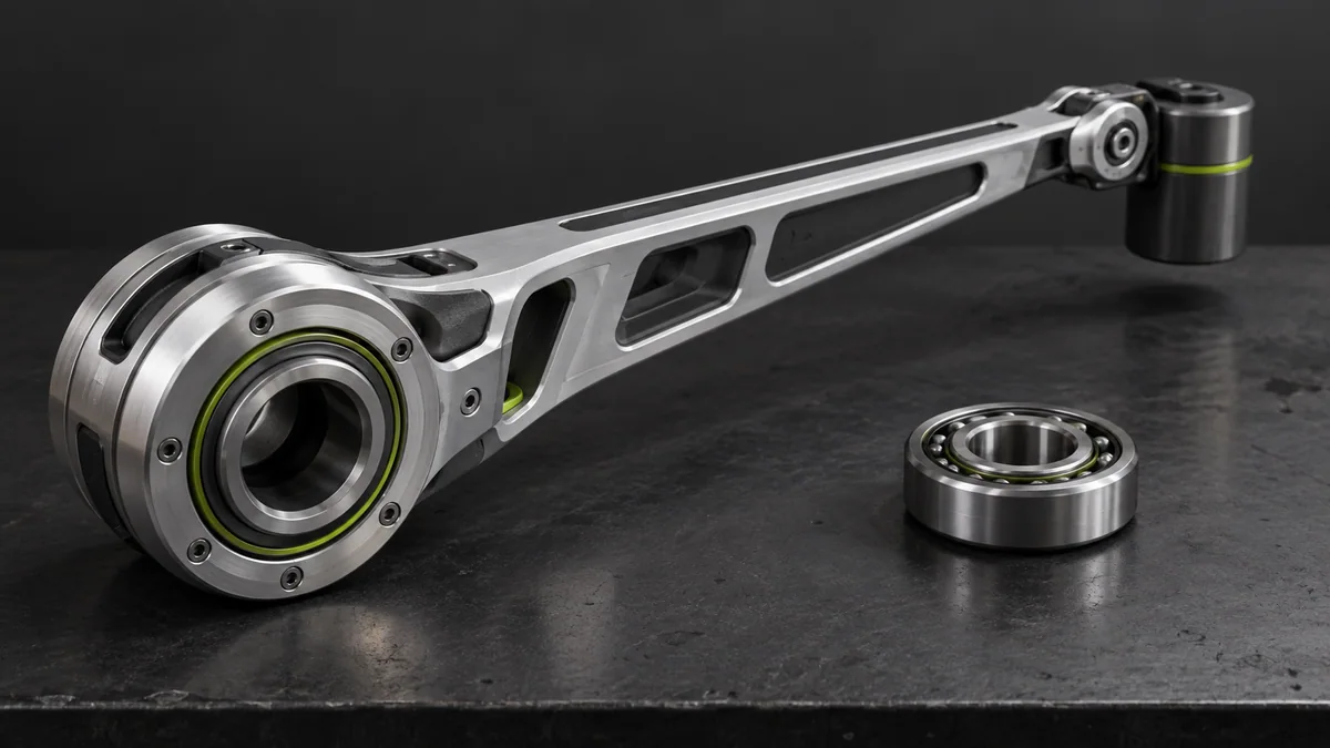
A 0.6 kg, 0.3 m uniform link has J=0.018 kg·m² about its end. A 0.2 kg tip mass adds 0.018 kg·m². At 4 rad/s², their combined acceleration torque is 0.144 N·m.
Try it step by step
- Choose the rotation axis and split the moving assembly into simple parts with known or estimated mass distributions.
- Calculate or extract each inertia about that same axis, using the parallel-axis theorem when needed.
- Multiply combined inertia by the required acceleration and combine with other torque contributions over the motion cycle.
- Refine the estimate using CAD and measured mass before selecting the final actuator.
How to check the result
Check that moving a tip mass inward reduces inertia quadratically with radius in the model.
Common mistake to avoid
Using only total mass with one arbitrary radius can misrepresent a distributed assembly. Inertia is axis-dependent.
Reference reading
Primary references for the underlying models, APIs or application context. The worked numbers and plots above are educational calculations, not results reported by these sources.