What you need
Use documented wire resistance per meter, one-way length and measured load current. Keep testing within the circuit’s protected low-voltage limits.
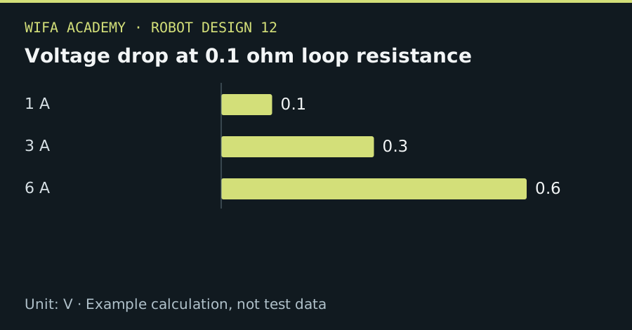
Read the diagram as a data table
| Condition or component | V |
|---|---|
| 1 A | 0.1 |
| 3 A | 0.3 |
| 6 A | 0.6 |
The calculation
R_loop = 2 × L × r_wire + R_contacts
ΔV = I × R_loop
P_loss = I² × R_loop
L is one-way meters, r_wire is Ω/m, R_contacts is total contact resistance and I is A.
Worked example
For L=2 m, r_wire=0.02 Ω/m, R_contacts=0.02 Ω and I=3 A, loop resistance is 0.10 Ω. Voltage drop is 0.30 V and cable-plus-contact loss is 0.90 W. At 6 A, drop doubles but heating becomes 3.6 W.
Try it step by step
- Trace the complete supply and return path and include each connector, protective device and switch contact.
- Calculate drop at normal and peak current, then compare the load voltage with its operating limits.
- Measure at the load during a representative transient, using instruments and probing methods appropriate to the circuit.
- Select wiring and connectors using current capacity, temperature, routing and protection requirements as well as voltage drop.
How to check the result
Investigate localized warm connections even when the total calculated drop appears acceptable.
Common mistake to avoid
This electrical calculation is not a cable-ampacity rule. Bundling, insulation, temperature and connector ratings can set stricter limits.
Reference reading
Primary references for the underlying models, APIs or application context. The worked numbers and plots above are educational calculations, not results reported by these sources.