What you need
Use a current-limited low-voltage source, a multimeter and datasheets. Do not apply unknown industrial or mains signals to this circuit.
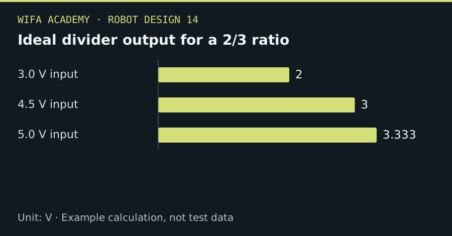
Read the diagram as a data table
| Condition or component | V |
|---|---|
| 3.0 V input | 2 |
| 4.5 V input | 3 |
| 5.0 V input | 3.333 |
The calculation
V_out = V_in × R₂ / (R₁ + R₂)
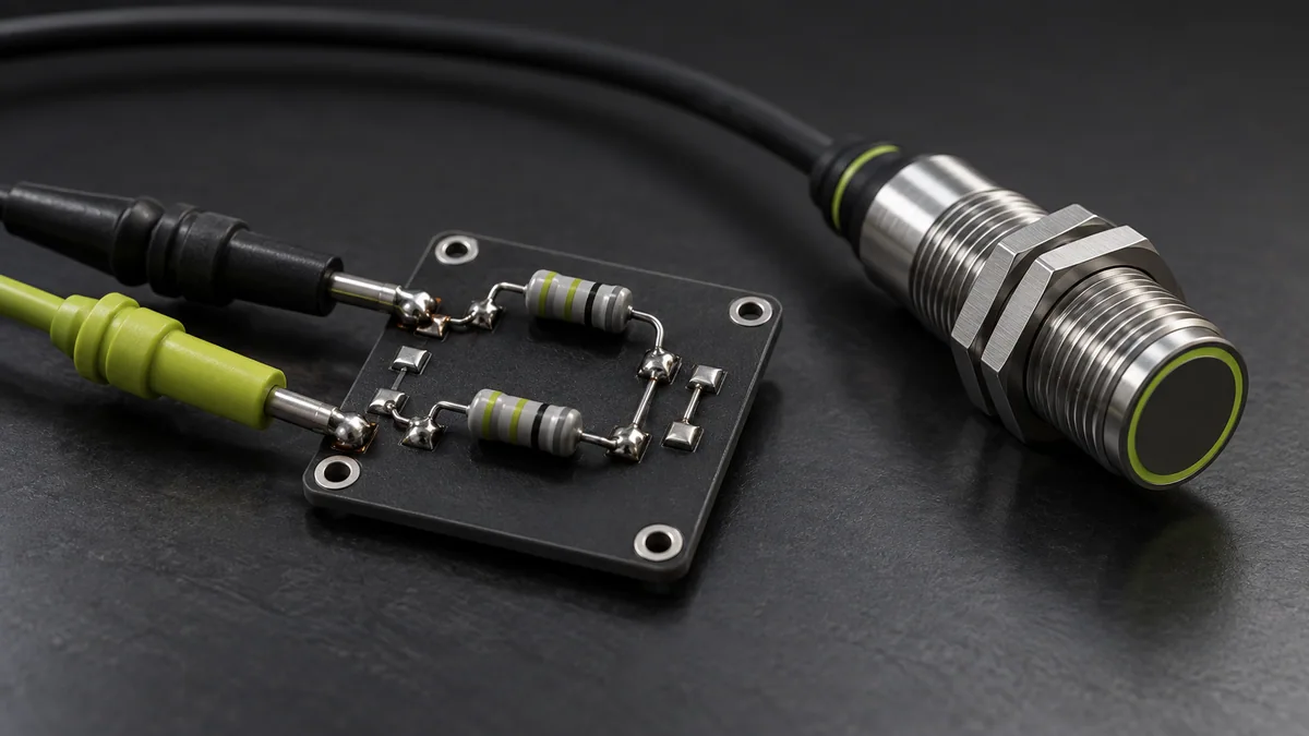
R₁ is the upper resistor from input to output and R₂ connects output to reference ground. The ideal model assumes negligible load current.
Worked example
For R₁=10 kΩ and R₂=20 kΩ, a 3 V input becomes 2 V and a 4.5 V input becomes 3 V. A 5 V input becomes 3.333 V, which may exceed a nominal 3.3 V ADC’s permitted input.
Try it step by step
- Check absolute maximum input, normal conversion range, grounding and sensor output-drive capability before selecting values.
- Choose the ratio with tolerance and worst-case sensor voltage included, rather than targeting the ADC limit exactly.
- Check source impedance against ADC sampling requirements and add appropriate protection using the device guidance.
- Measure the divider across the expected input range before connecting it to the microcontroller.
How to check the result
The worst-case output must stay within allowed limits, and measured conversion settling should satisfy the required sampling behavior.
Common mistake to avoid
A divider can load a high-impedance sensor. It is not a safe general interface for 24 V industrial signals, isolation barriers or fault conditions.
Reference reading
Primary references for the underlying models, APIs or application context. The worked numbers and plots above are educational calculations, not results reported by these sources.