What you need
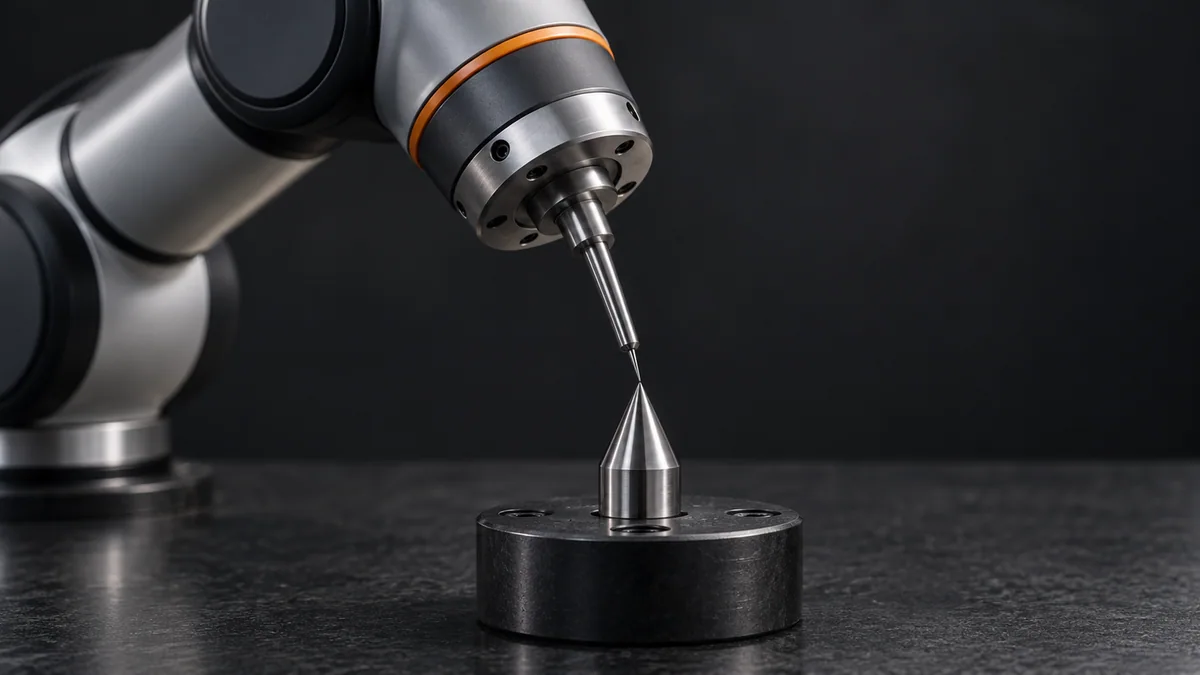
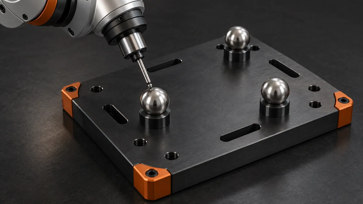
Use three suitable non-collinear fixture references or the controller’s prescribed frame-teaching method. Start with an offline coordinate worksheet.
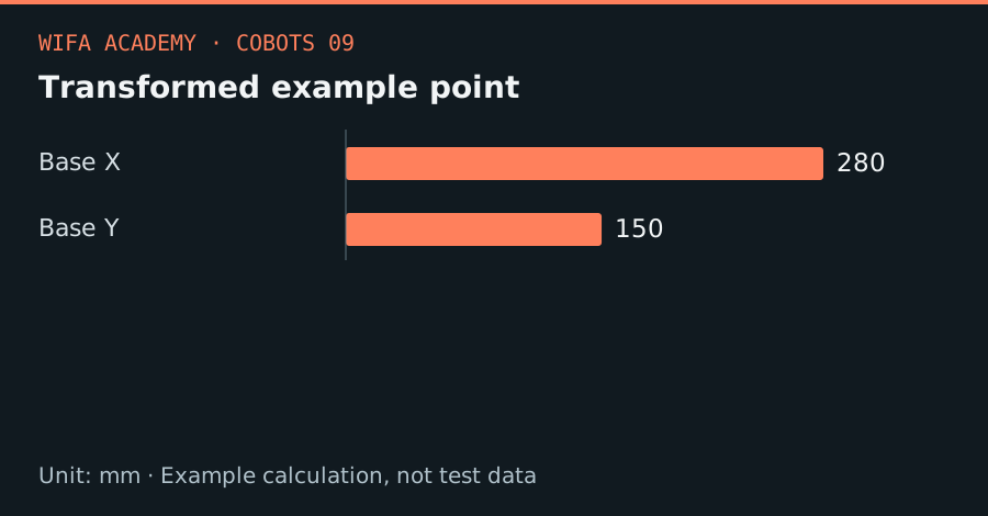
Read the diagram as a data table
| Condition or component | mm |
|---|---|
| Base X | 280 |
| Base Y | 150 |
The calculation
p_base = R_base_fixture × p_fixture + t_base_fixture
p is a 3D position vector, R is a rotation matrix, and t is a translation vector. All distances must use the same units.
Worked example
Take a fixture rotated 90° about base Z and translated by (300, 100, 0) mm. A fixture point (50, 20, 0) becomes (-20, 50, 0) before translation, then (280, 150, 0) mm in the base frame.
Try it step by step
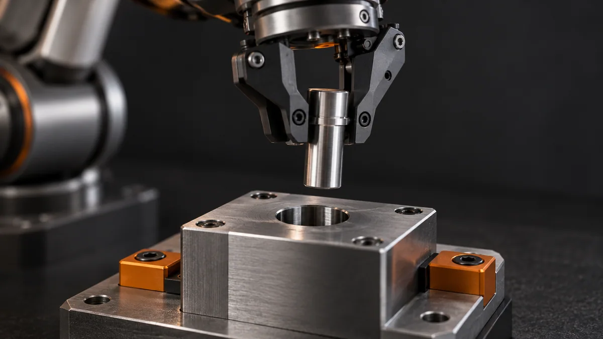
- Choose repeatable physical references on the fixture and document the positive x and y directions with a drawing.
- Teach or measure the frame using the supported controller procedure, avoiding nearly collinear reference points.
- Transform several known fixture points independently and check that the signs and rotation direction match the robot display.
- Validate approach and retreat paths after any frame update; moving targets can also move paths toward surrounding equipment.
How to check the result
Check an unused reference near each corner of the fixture. A frame that matches only its origin may still have an orientation error.
Common mistake to avoid
Adding a translation to every point is insufficient after a fixture rotation. Never reuse a frame name without verifying its current definition.
Reference reading
Primary references for the underlying models, APIs or application context. The worked numbers and plots above are educational calculations, not results reported by these sources.