What you need
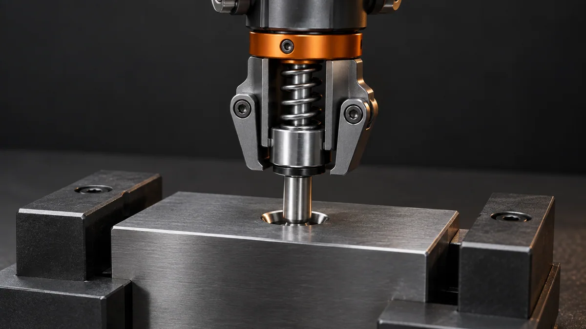
Use a spring-contact simulator or an unpowered bench fixture. Define an insertion axis, travel bound and representative compliance.
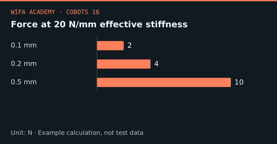
Read the diagram as a data table
| Condition or component | N |
|---|---|
| 0.1 mm | 2 |
| 0.2 mm | 4 |
| 0.5 mm | 10 |
The calculation
F = k × δ
F is force in N, k is effective stiffness in N/mm, and δ is compression in mm within the linear range.
Worked example
At 20 N/mm effective stiffness, 0.2 mm compression produces 4 N, while 0.5 mm produces 10 N. If the effective stiffness rises to 100 N/mm, the same 0.5 mm error produces 50 N. Small alignment errors can matter greatly.
Try it step by step
- Model the tool, fixture and part compliance along the insertion axis; use a measured stiffness range where possible.
- Simulate small alignment offsets and log force versus travel, including the condition where contact occurs too early.
- Define bounded process behavior for abnormal force, missing insertion and sensor faults; keep safety functions independent.
- Have a competent integrator review the real insertion and validate it using the manufacturer’s supported force-control procedures.
How to check the result
A valid experiment should distinguish normal seating from a jam using force and displacement together, not a single final force value.
Common mistake to avoid
A low process-force setting is not proof of safe human contact. Sensor delays, controller response and trapping geometry remain important.
Reference reading
Primary references for the underlying models, APIs or application context. The worked numbers and plots above are educational calculations, not results reported by these sources.