What you need
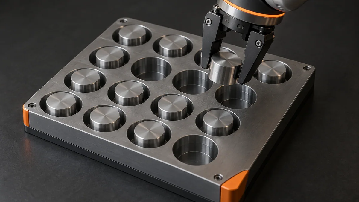
Measure pocket pitch and choose a tray-frame origin. Use dummy coordinates in a spreadsheet or simulator before teaching hardware.
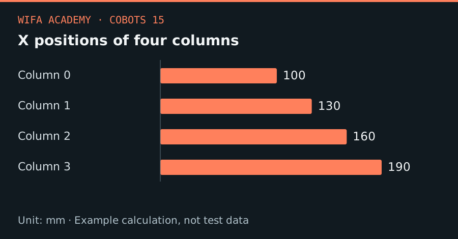
Read the diagram as a data table
| Condition or component | mm |
|---|---|
| Column 0 | 100 |
| Column 1 | 130 |
| Column 2 | 160 |
| Column 3 | 190 |
The calculation
x(i,j) = x₀ + i × p_x
y(i,j) = y₀ + j × p_y
i and j are zero-based column and row indices; p_x and p_y are pitch in mm. Positions are local to the tray frame.
Worked example
For origin (100, 50) mm and pitch (30, 25) mm, pocket i=2, j=1 lies at (160, 75) mm. A 4-column by 3-row tray contains 12 pockets, with final local x=190 mm and y=100 mm.
Try it step by step
- Measure the first and last pocket to check cumulative pitch error instead of trusting a nominal drawing alone.
- Generate all coordinates offline and inspect row order, index limits and the chosen empty-pocket handling rule.
- Add approach and retreat heights as distinct poses and transform the tray coordinates through its measured fixture frame.
- Validate the corner pockets and the loaded tool’s clearance before a supervised dry run of the full pattern.
How to check the result
Print the generated pocket list and verify it against physical pocket numbering. The final count and corner coordinates must match the drawing.
Common mistake to avoid
Mixing one-based human labels with zero-based code shifts every target. Never use a tray loop without bounds checks and a valid occupancy state.
Reference reading
Primary references for the underlying models, APIs or application context. The worked numbers and plots above are educational calculations, not results reported by these sources.