What you need
Measure the loaded tool’s mass and perpendicular center-of-gravity offset. Keep the robot disabled while inspecting dimensions.
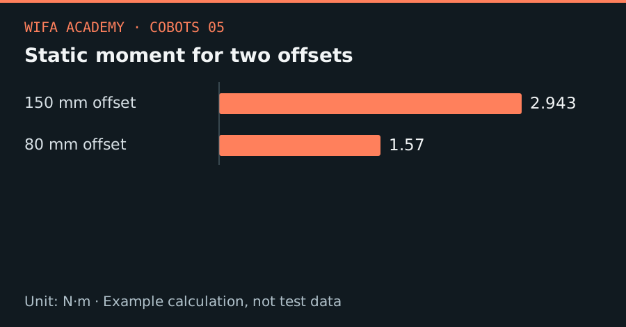
Read the diagram as a data table
| Condition or component | N·m |
|---|---|
| 150 mm offset | 2.943 |
| 80 mm offset | 1.57 |
The calculation
M = m × g × d_perp
M is moment in N·m, m is kg, g = 9.81 m/s², and d_perp is the perpendicular lever arm in m.
Worked example
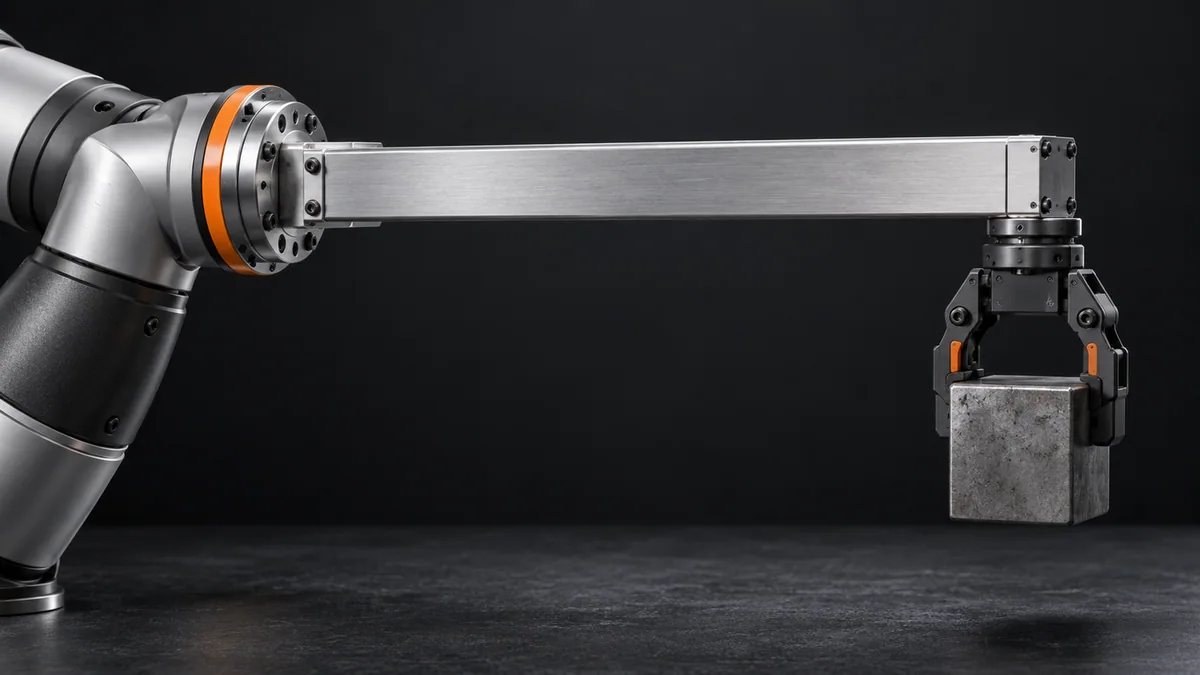
A 2 kg tool with a 0.15 m horizontal lever arm creates 2.943 N·m under gravity. Shortening the offset to 0.08 m reduces this to 1.570 N·m. Neither value includes acceleration or the tool’s distributed rotational inertia.
Try it step by step
- Draw the gravity force line and the wrist axis in the demanding pose; measure the perpendicular distance between them.
- Calculate static moment for the heaviest workpiece and for every orientation that could produce a larger lever arm.
- Move heavy adapters closer to the flange or redesign the tool before increasing robot size solely on a mass comparison.
- Check dynamic and load-diagram limits with the manufacturer’s data, then validate the selected trajectory under supervision.
How to check the result
The finished worksheet should include mass, center of gravity, inertia and the demanding pose, not a single torque number.
Common mistake to avoid
Using total tool length instead of the perpendicular center-of-gravity offset gives the wrong static moment. Gravity moment can change greatly with pose.
Reference reading
Primary references for the underlying models, APIs or application context. The worked numbers and plots above are educational calculations, not results reported by these sources.