What you need
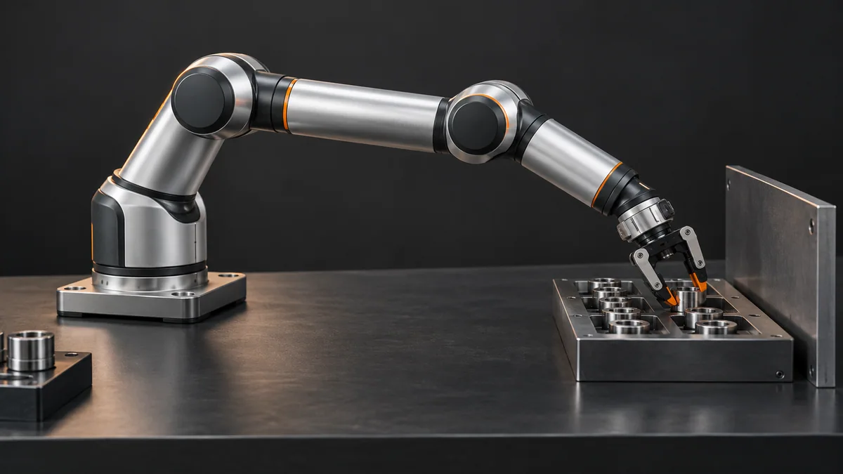
Use a measured cell layout, tool length and the manufacturer’s simulator. Include walls, guards, fixtures and cable space.
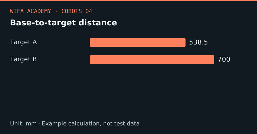
Read the diagram as a data table
| Condition or component | mm |
|---|---|
| Target A | 538.5 |
| Target B | 700 |
The calculation
r = √(x² + y² + z²)
x, y and z are target coordinates relative to the base in mm. r is a geometric distance, not a full kinematic reach test.
Worked example
A target at (400, 300, 200) mm is 538.5 mm from the base origin. A second target at (600, 300, 200) mm is 700 mm away. These numbers are useful for comparing layouts, but neither proves a valid wrist pose.
Try it step by step
- Mark pick, place and pre-approach tool poses on the same measured drawing; include the full tool orientation.
- Compute rough base-to-target distances for candidate base positions and discard layouts beyond the specified envelope.
- Solve complete poses in the simulator and inspect elbow, wrist, joint limits and the tool’s swept volume.
- Check loading access and cable routing before fixing the base; a reachable cell can still be impossible to maintain.
How to check the result
Save a collision-checked path for each part variant and verify physical fixture coordinates before permitting automatic motion.
Common mistake to avoid
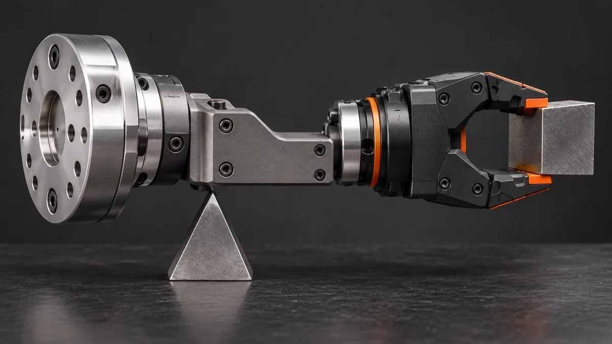
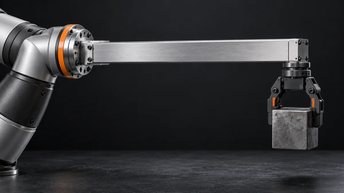
Do not compare tool-tip distance directly with a flange-only reach specification without accounting for the manufacturer’s definition and tool geometry.
Reference reading
Primary references for the underlying models, APIs or application context. The worked numbers and plots above are educational calculations, not results reported by these sources.