What you need
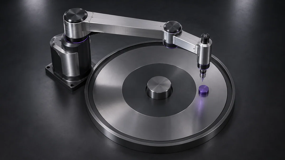
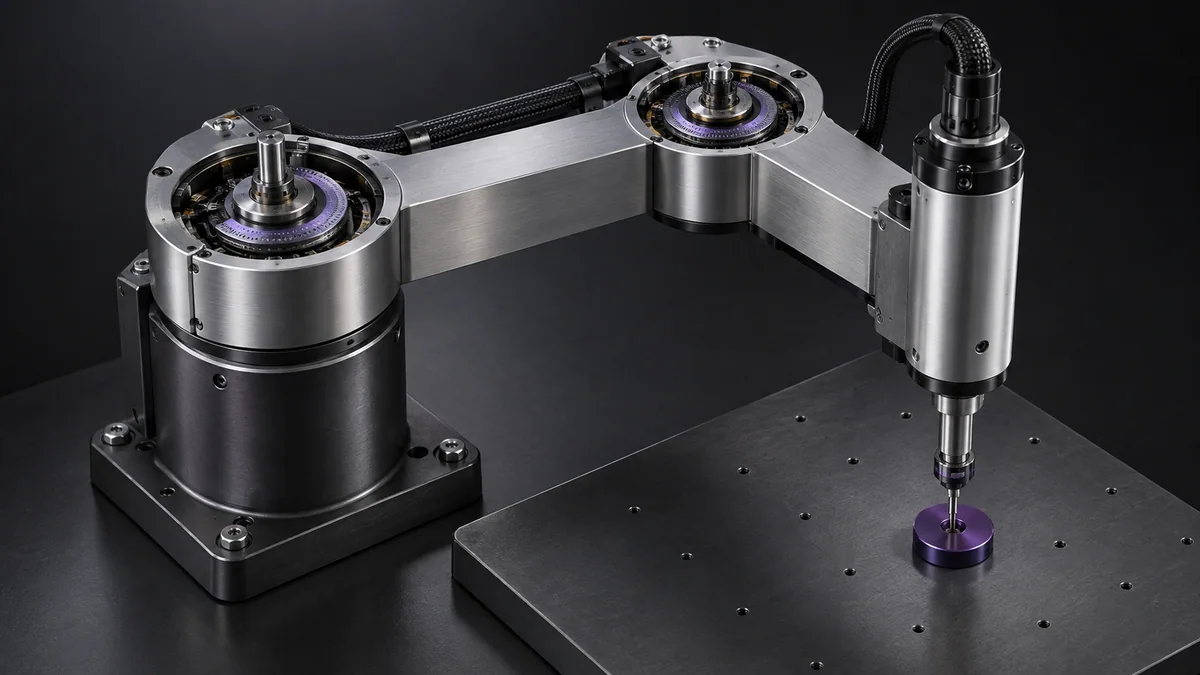
Use a paper sketch or simulator with four independently labeled joint coordinates. No powered hardware is needed.

Read the diagram as a data table
| Condition or component | degrees magnitude |
|---|---|
| Shoulder +30 | 30 |
| Elbow +60 | 60 |
| Wrist -90 | 90 |
The calculation
q = [θ₁, θ₂, z, θ₄]
ψ = θ₁ + θ₂ + θ₄
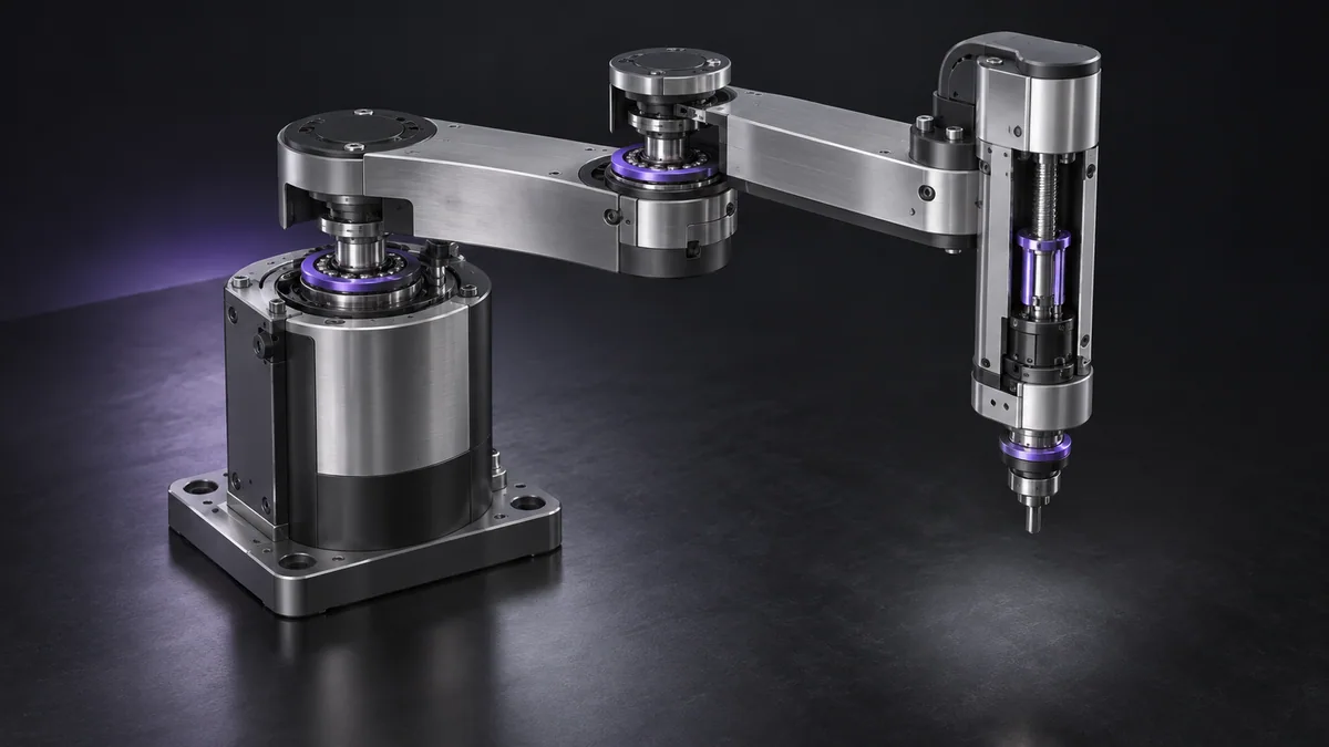
θ values are joint angles in a consistent convention, z is vertical translation and ψ is tool yaw for the simplified serial-axis model.
Worked example
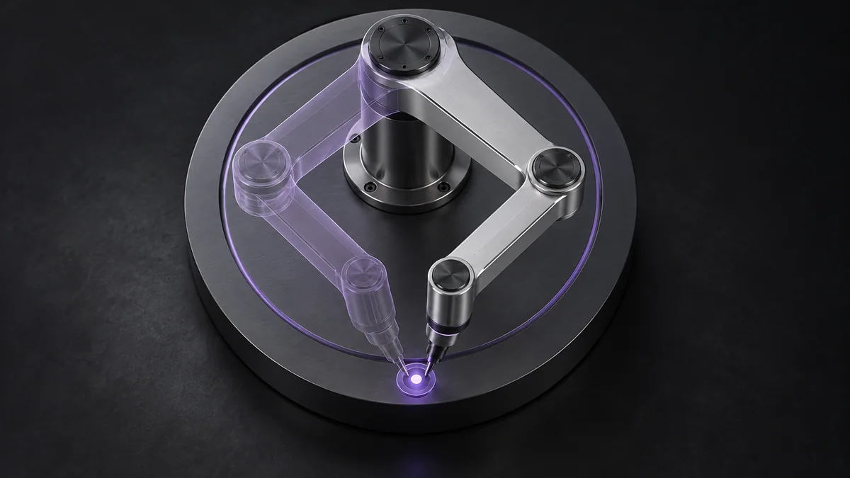
With shoulder 30°, elbow 60° and wrist -90°, tool yaw is 0°. Changing the elbow to 40° while leaving the other axes unchanged gives -20° yaw. The tool orientation is affected by the arm, not only the wrist.
Try it step by step
- Write the required x, y, z and yaw ranges and explicitly state whether the task ever needs tool roll or pitch.
- Label every joint’s positive direction and zero position on a top and side view.
- Move one joint at a time in simulation and observe which tool coordinates change.
- Check whether the selected machine has mechanical coupling or controller conventions that differ from this simple model.
How to check the result
The model should reproduce a few known poses and demonstrate all required task orientations without adding imaginary degrees of freedom.
Common mistake to avoid
Some SCARA mechanisms couple vertical and rotary motion. Read the actual machine kinematic definition before translating these coordinates into drive commands.
Reference reading
Primary references for the underlying models, APIs or application context. The worked numbers and plots above are educational calculations, not results reported by these sources.