What you need
Use a dimensioned cell layout and a two-link simulator. Measure distances from the intended shoulder axis.
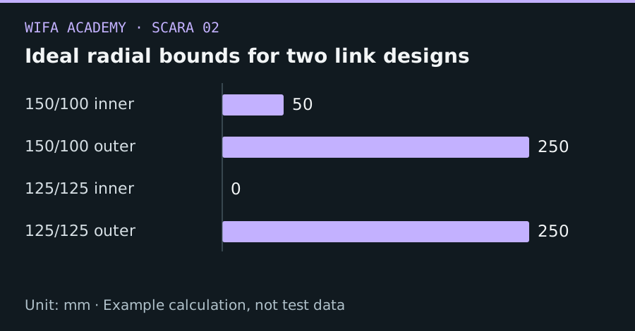
Read the diagram as a data table
| Condition or component | mm |
|---|---|
| 150/100 inner | 50 |
| 150/100 outer | 250 |
| 125/125 inner | 0 |
| 125/125 outer | 250 |
The calculation
r_min = |L₁ − L₂|
r_max = L₁ + L₂
L₁ and L₂ are link lengths in mm. These bounds assume unrestricted planar joint rotation and ignore collisions and tool offsets.
Worked example
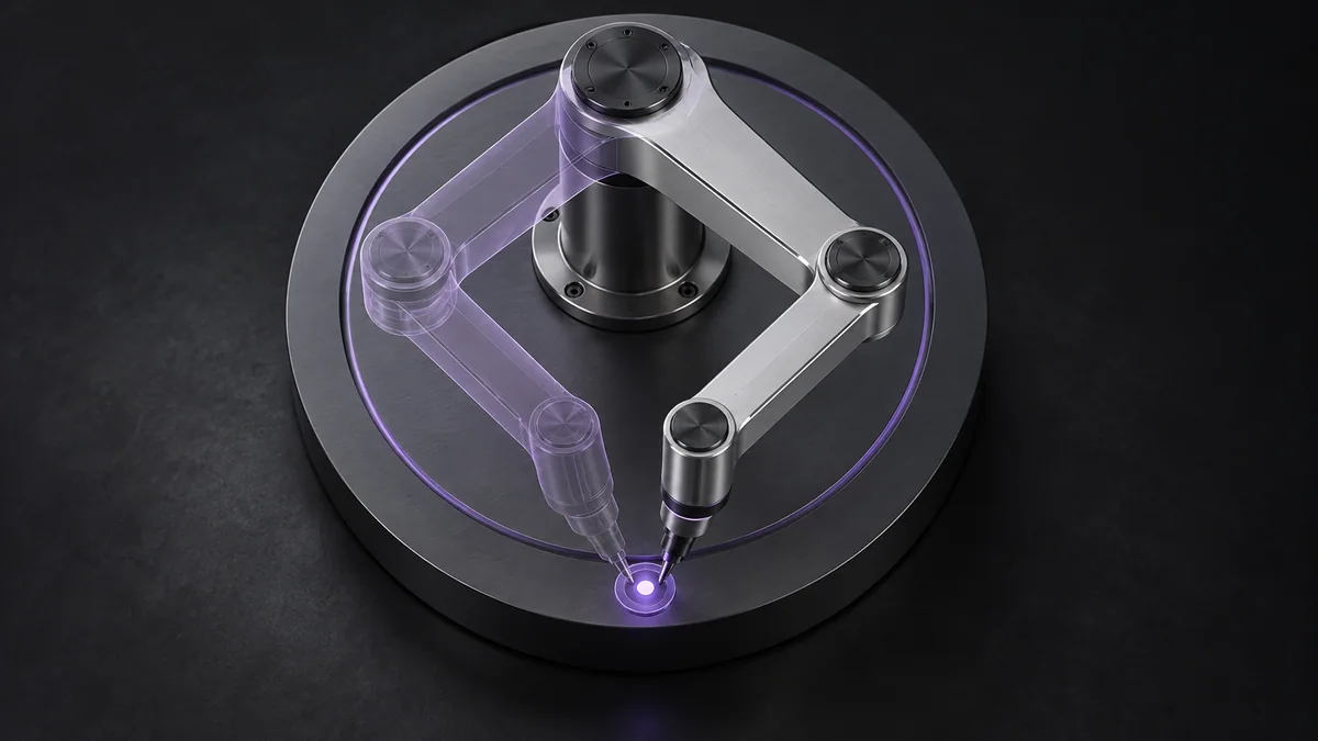
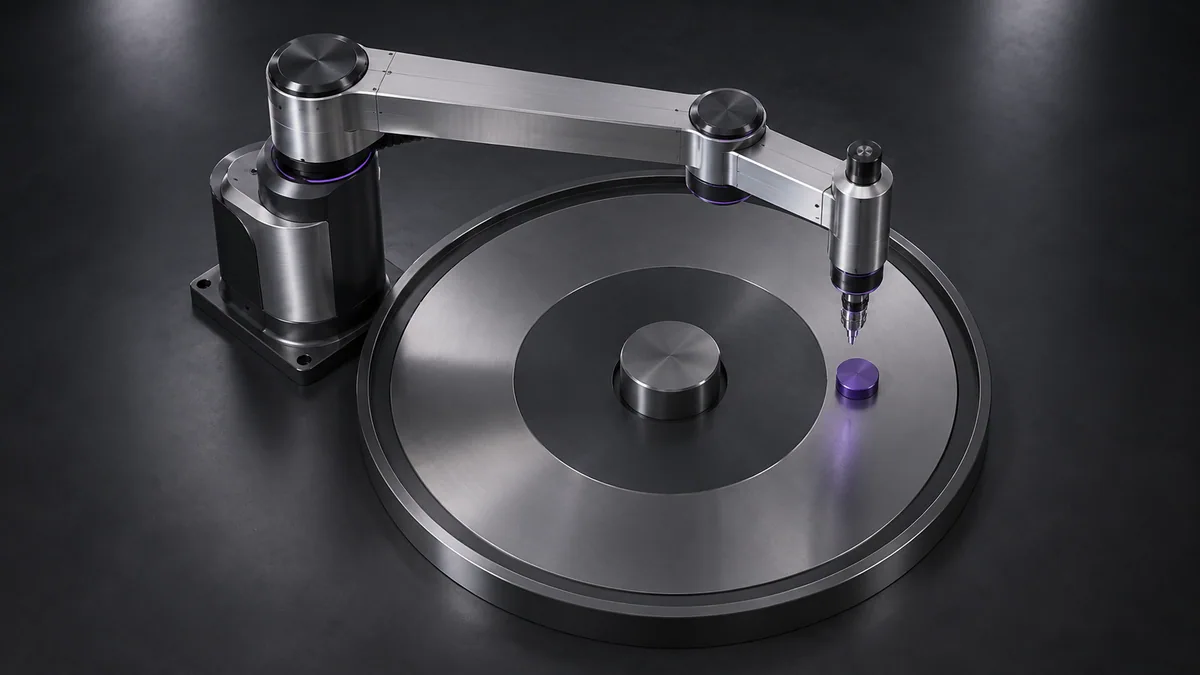
Links of 150 and 100 mm give ideal radii from 50 to 250 mm. Equal 125 mm links also reach 250 mm, but their ideal inner radius is zero. Real joints and the base may still prevent access near the center.
Try it step by step
- Plot all pick, place and approach locations relative to candidate base positions.
- Compare link-length pairs using inner and outer bounds, including the full carried tool geometry.
- Apply actual joint limits and collision envelopes in simulation to obtain a usable rather than purely geometric workspace.
- Place frequent work away from full extension and inspect velocity amplification at demanding points.
How to check the result
Save the reachable region with joint limits applied and verify every required pose and approach, not just its x-y location.
Common mistake to avoid
The annulus is only an ideal position envelope. It says nothing about obstacle clearance, wrist orientation or allowable joint speed near singularities.
Reference reading
Primary references for the underlying models, APIs or application context. The worked numbers and plots above are educational calculations, not results reported by these sources.