What you need
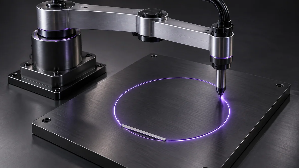
Use an offline circle generator with known radius and workspace center. Keep the tool path away from singular and colliding configurations.
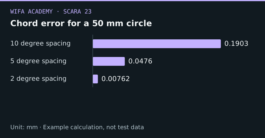
Read the diagram as a data table
| Condition or component | mm |
|---|---|
| 10 degree spacing | 0.1903 |
| 5 degree spacing | 0.0476 |
| 2 degree spacing | 0.00762 |
The calculation
x = c_x + R cos φ; y = c_y + R sin φ
e_chord = R × [1 − cos(Δφ/2)]
R and e_chord use the same length unit. Δφ is angular spacing in radians for each straight chord.
Worked example
For a 50 mm radius, 10° spacing gives about 0.190 mm chord error. At 5° spacing, error falls to 0.0476 mm. The smaller step requires more segments and still needs suitable speed planning.
Try it step by step
- Choose a circle center and radius entirely within the usable workspace, including approach and exit paths.
- Calculate a sampling interval from the permitted geometric deviation rather than choosing an arbitrary point count.
- Solve and validate joint configurations along the circle, preserving branch continuity.
- Apply smooth timing and inspect acceleration and controller interpolation behavior at segment boundaries.
How to check the result
Compare the executed path with the ideal circle and report both radial error and speed variation.
Common mistake to avoid
If the controller stops at each segment, a dense point list can produce a slow, jerky path. Use its supported circular or continuous-path features when available.
Reference reading
Primary references for the underlying models, APIs or application context. The worked numbers and plots above are educational calculations, not results reported by these sources.