What you need
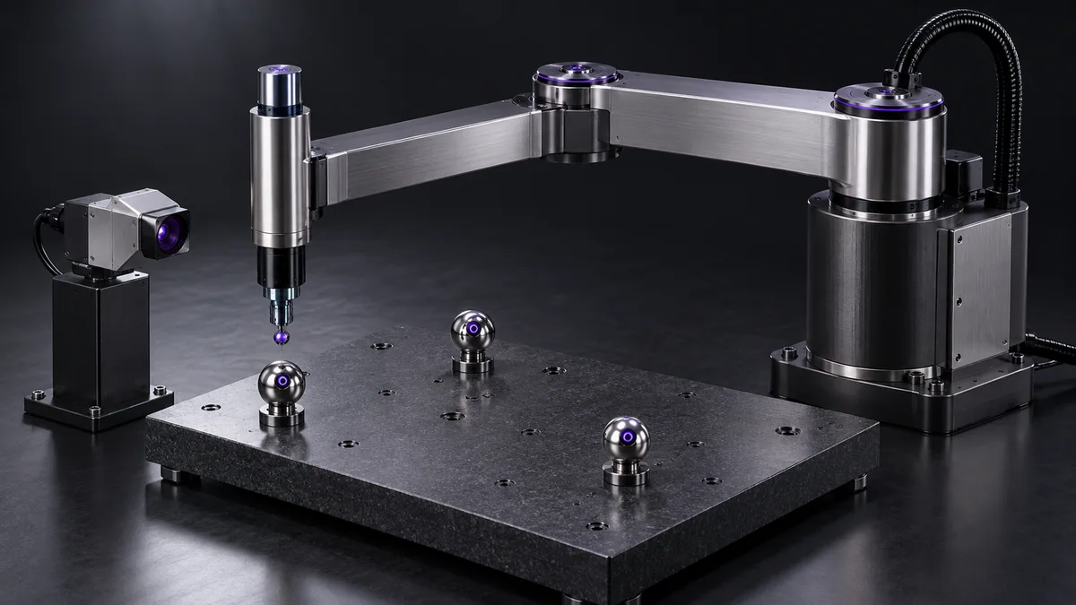
Use an independent coordinate measurement method and several well-spaced unpowered or safely measured robot configurations.
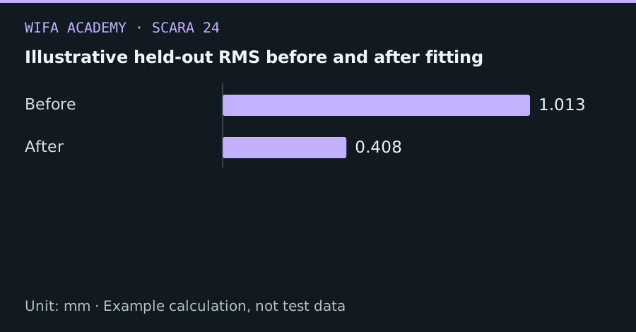
Read the diagram as a data table
| Condition or component | mm |
|---|---|
| Before | 1.013 |
| After | 0.408 |
The calculation
cost = Σ||p_measured,i − FK(q_i, parameters)||²
Parameters may include link lengths and joint-zero offsets. The residual is in squared length units and should be checked on held-out poses.
Worked example
Illustrative held-out errors of 0.8, 1.0 and 1.2 mm have RMS 1.013 mm. After a hypothetical calibration, 0.3, 0.4 and 0.5 mm give RMS 0.408 mm. These numbers demonstrate reporting, not a measured improvement.
Try it step by step
- Measure joint-center geometry and establish reasonable parameter bounds before fitting.
- Collect diverse poses with accurate joint readings and independent tool-position measurements, avoiding only straight-arm configurations.
- Fit a small identifiable parameter set and inspect whether fitted values remain physically plausible.
- Validate on unused poses and compare residual patterns; load-dependent error may require a compliance model rather than altered link lengths.
How to check the result
A useful calibration improves independent residuals without producing implausible geometry or hiding direction-dependent mechanical errors.
Common mistake to avoid
Optimizing many parameters on a few noisy points can overfit. A better training residual is not sufficient evidence of better positioning.
Reference reading
Primary references for the underlying models, APIs or application context. The worked numbers and plots above are educational calculations, not results reported by these sources.