What you need
Collect sensor width, desired object field width and working distance. Use the lens manufacturer’s data for final selection.
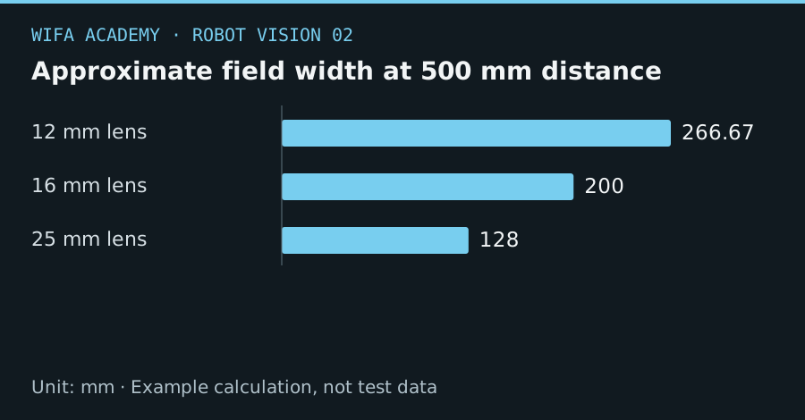
Read the diagram as a data table
| Condition or component | mm |
|---|---|
| 12 mm lens | 266.67 |
| 16 mm lens | 200 |
| 25 mm lens | 128 |
The calculation
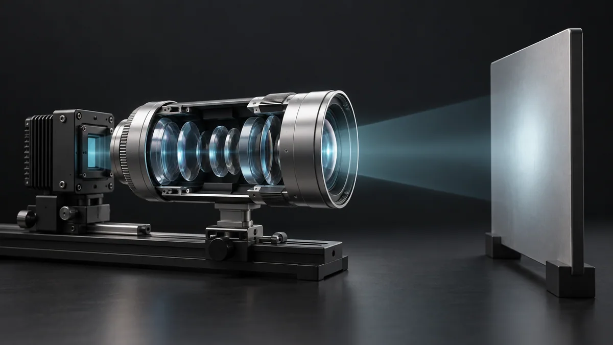
f ≈ S × Z / W
f is focal length in mm, S is sensor width in mm, Z is working distance in mm and W is object field width in mm.
Worked example
For a 6.4 mm sensor width, 500 mm working distance and 200 mm object field, f is about 16 mm. At the same distance, a 12 mm lens gives approximately 267 mm field and a 25 mm lens about 128 mm.
Try it step by step
- Measure the available camera-to-object distance from the appropriate lens reference, allowing for the robot and tool envelope.
- Compute a candidate focal length and check sensor-format compatibility and minimum focus distance in the lens specification.
- Mount the candidate and measure actual field width with a ruler at the working plane rather than trusting the approximation.
- Lock focus and aperture after testing depth variation, contrast and edge quality throughout the required area.
How to check the result
The final image should contain all required parts with margin while preserving enough pixels on the smallest feature.
Common mistake to avoid
The approximation becomes less accurate at close focus. Changing focus or zoom after calibration can invalidate the intrinsic model.
Reference reading
Primary references for the underlying models, APIs or application context. The worked numbers and plots above are educational calculations, not results reported by these sources.