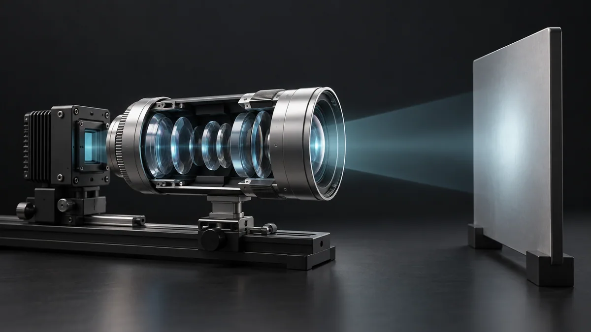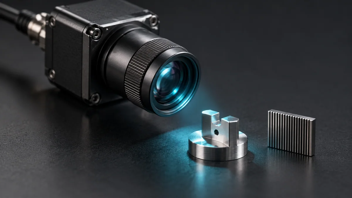
What you need
Use a measured part, a target with fine features and a camera mounted at the intended working distance.
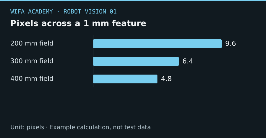
Read the diagram as a data table
| Condition or component | pixels |
|---|---|
| 200 mm field | 9.6 |
| 300 mm field | 6.4 |
| 400 mm field | 4.8 |
The calculation
s = W / N
p_feature = w / s
W is horizontal field of view in mm, N is horizontal pixels, s is mm/pixel and w is feature width in mm.
Worked example
A 200 mm field over 1,920 pixels gives 0.1042 mm/pixel. A 1 mm feature spans 9.6 pixels. Expanding the field to 400 mm leaves only 4.8 pixels on that feature, even though the camera resolution has not changed.
Try it step by step
- Define the smallest feature and the localization tolerance separately; seeing a part is easier than measuring its edge precisely.
- Calculate approximate scale for the desired field of view and check that the whole part remains visible under expected offsets.
- Capture real images at the selected distance, exposure and focus, then examine the feature at original resolution.
- Measure repeated localization error on a separate target set, including positions near the image edges.
How to check the result
Accept the imaging setup on measured detection and position error, not a pixel-count rule alone. Keep example target distances and lighting in the record.
Common mistake to avoid
Pixel scale is not measurement accuracy. Lens blur, distortion, noise and calibration uncertainty can dominate a seemingly generous resolution.
Reference reading
Primary references for the underlying models, APIs or application context. The worked numbers and plots above are educational calculations, not results reported by these sources.