What you need
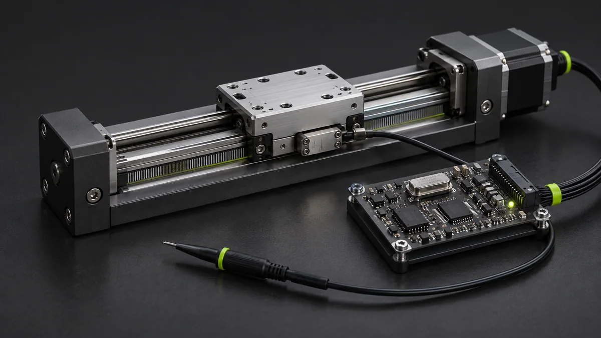
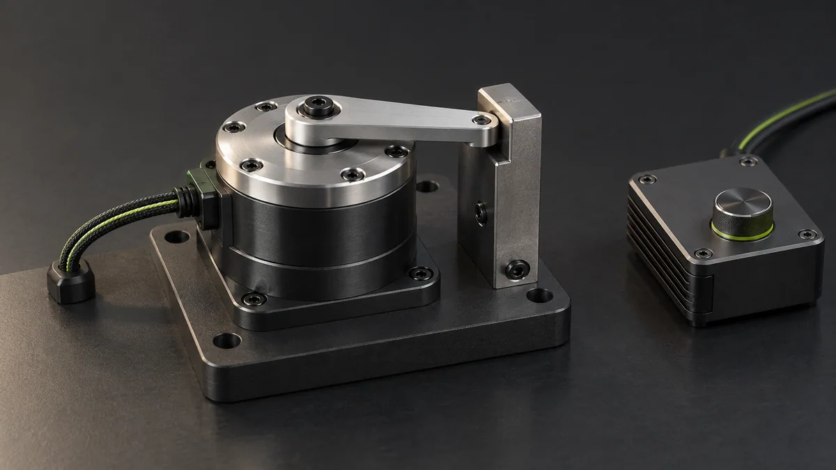
Use a simple simulated axis with position feedback and a known actuator-command limit. Do not tune a real arm by trial and error around people.
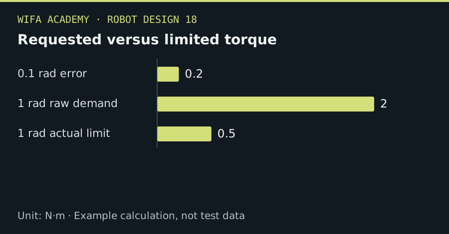
Read the diagram as a data table
| Condition or component | N·m |
|---|---|
| 0.1 rad error | 0.2 |
| 1 rad raw demand | 2 |
| 1 rad actual limit | 0.5 |
The calculation
e = target − measured
u_raw = K_p × e
u = clamp(u_raw, −u_max, u_max)
K_p units depend on the commanded quantity. For a torque command and angle in radians, gain is N·m/rad.
Worked example
With K_p=2 N·m/rad, a 0.1 rad error requests 0.2 N·m. A 1 rad error requests 2 N·m, but a 0.5 N·m actuator limit clips the actual command. Larger gain cannot bypass that limit.
Try it step by step
- Verify feedback sign in simulation; positive command must reduce the intended error under the chosen convention.
- Include inertia, damping, delay and command limits in the model before comparing gains.
- Inspect overshoot, settling and steady-state error under representative loads.
- Use the manufacturer’s approved tuning and protection procedures for any hardware implementation.
How to check the result
The controller should remain bounded and respond predictably to large target steps, disturbances and invalid feedback.
Common mistake to avoid
A simple proportional position loop may retain load-dependent error and can oscillate at excessive gain. Gain selection requires the actual plant dynamics.
Reference reading
Primary references for the underlying models, APIs or application context. The worked numbers and plots above are educational calculations, not results reported by these sources.